Overhead console and vehicle-body upper structure

a technology for overhead consoles and vehicles, applied in vehicle spotlighting, transportation and packaging, lighting and heating apparatus, etc., can solve the problems of reducing the design property of overhead consoles, leakage of light that cannot reach the light exit surface directly, and the length of light guiding members that are sufficient to form a sufficiently long optical path may not be provided inside a flat overhead console, etc. , to achieve the effect of reducing the peak of luminance distribution of light exit surfaces during lighting of map lamps,

Active Publication Date: 2020-02-25
TOYOTA JIDOSHA KK
View PDF42 Cites 1 Cited by
  • Summary
  • Abstract
  • Description
  • Claims
  • Application Information

AI Technical Summary

Benefits of technology

The present disclosure provides an overhead console and a vehicle-body upper structure each of which is able to restrain an occurrence of glare due to a light source as appropriate.
In this regard, the light guiding member provided in the above overhead console is formed in a shape extending with the bending portions provided at intermediate positions in thereof. Further, the light guiding member has such a shape that line segments that can be drawn between given points on the light incident surface and given points on the light exit surface do not include a line segment that passes through only the light guiding member, that is, a shape in which an optical path that linearly connects the light incident surface to the light exit surface cannot be formed thereinside. In such a light guiding member, the light incident on the light incident surface reaches the light exit surface through a path bending along the shape of the light guiding member. Accordingly, even inside the flat overhead console, the light guiding member having a sufficiently long optical path formed therein from the light incident surface to the light exit surface can be provided. Further, in such a case, even if the light exit surface is not configured such that the light exit surface is hardly visible from outside, an occurrence of glare due to the light source can be restrained. Accordingly, a degree of freedom of appearance design of the overhead console is not spoiled due to anti-glare measures. Accordingly, with the overhead console, it is possible to appropriately restrain the occurrence of glare due to the light source.
In the above aspect, a partition wall made of an opaque material may be provided inside the overhead console so as to intersect with all line segments that do not pass through the light incident surface among the line segments drawn between the given points on the light-emitting surface and the given points on the light exit surface. Even with the above configuration, unevenness in luminance of the light exit surface due to leak light from the light source can be restrained. That is, if the partition wall is provided, the leak light from the light source is blocked by the partition wall, so that the leak light cannot reach the light exit surface directly. Hereby, the emission of the leak light from the light exit surface can be restrained.
In a map lamp that throws light on a limited range, the directivity of the emission light is strong, and light may be hardly emitted outside an irradiation range of the map lamp during lighting. In such a case, depending on its surrounding brightness, it might be difficult to check whether the map lamp is turned on or off when the light exit surface is viewed from outside the irradiation range of the map lamp. In this regard, the light exit surface may be constituted by a flat portion constituted by a flat surface perpendicular to a front-face direction of the light exit surface, and a cut face portion constituted by a surface inclined to the flat portion so as to divide the flat portion into a plurality of regions. In such a case, while the light is emitted within the irradiation range of the map lamp through the flat portion, the light can be also emitted in directions other than the irradiation range of the map lamp through the cut face portion, thereby making it possible to easily check whether the map lamp is turned on or not.

Problems solved by technology

In such a case, a deep recess is formed on the design surface of the overhead console, so that its design property decreases.
However, in a case where the light guiding member has a straight shape without a bending portion, the light guiding member with a length sufficient enough to form a sufficiently long optical path may not be provided inside a flat overhead console.
That is, if the partition wall is provided, the leak light from the light source is blocked by the partition wall, so that the leak light cannot reach the light exit surface directly.
Note that it might be difficult that the entire light exit surface is irradiated with light with sufficient brightness by only one light source.
Further, it might be difficult to secure necessary illuminance by only one light source.
In such a case, depending on its surrounding brightness, it might be difficult to check whether the map lamp is turned on or off when the light exit surface is viewed from outside the irradiation range of the map lamp.
In the meantime, if leak light from the light source, which is not incident on the light incident surface of the light guiding member, reaches the eyes of the occupant through the light exit surface, unevenness might be caused in the luminance of the light exit surface when viewed from the occupant.

Method used


Image

  • Overhead console and vehicle-body upper structure
  • Overhead console and vehicle-body upper structure
  • Overhead console and vehicle-body upper structure

Examples


Embodiment Construction

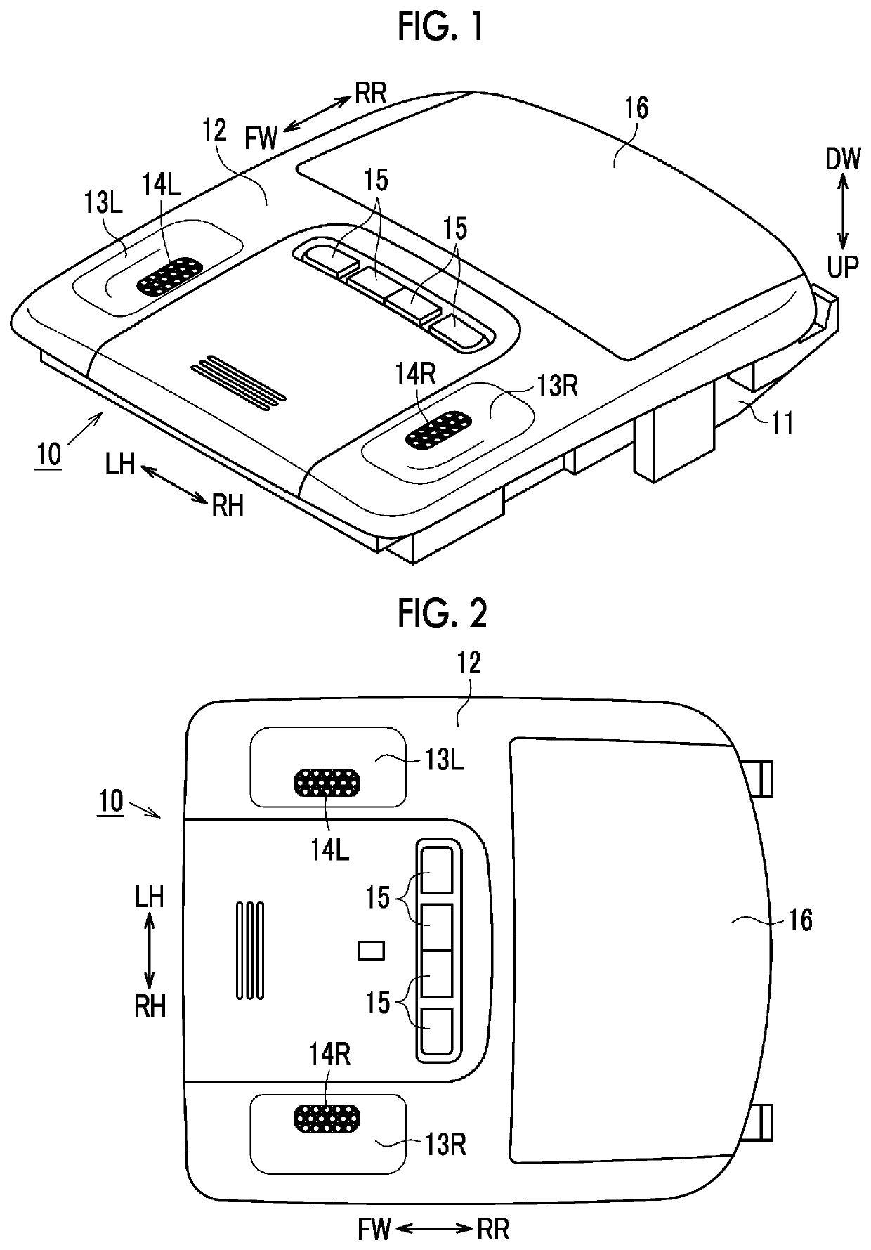
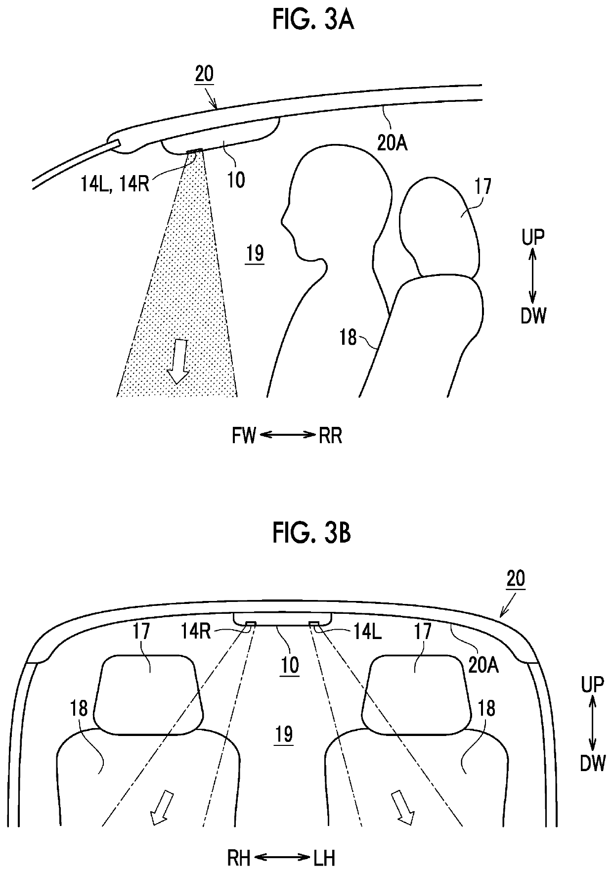
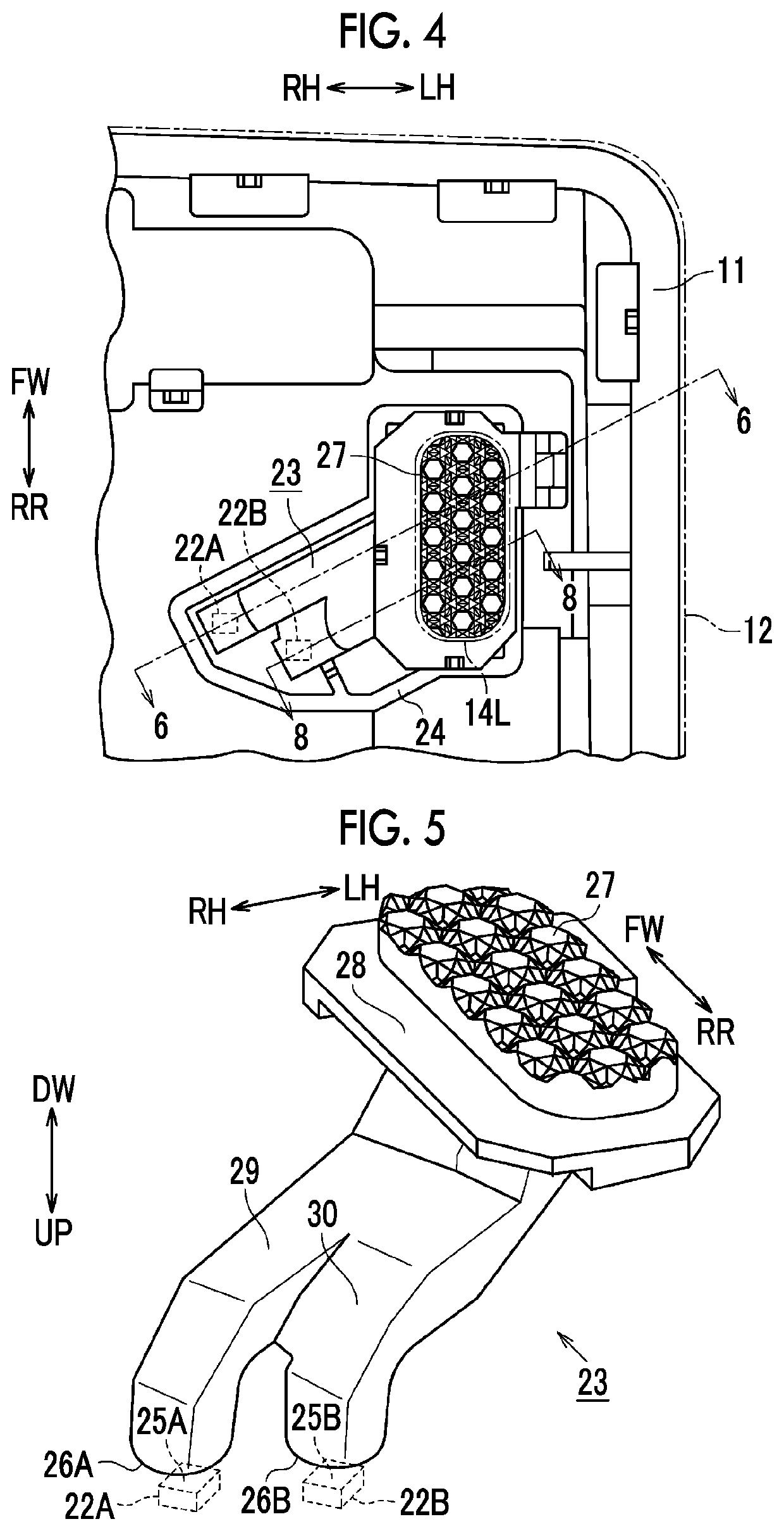
The following description describes one embodiment of an overhead console and a vehicle-body upper structure in detail with reference to FIGS. 1 to 14. Note that, in each figure to be referred to in the following description, in the vehicle-body upper structure or the overhead console assembled to the vehicle-body upper structure, a direction toward a vehicle-body front side is indicated by an arrow FW, a direction toward a vehicle-body rear side is indicated by an arrow RR, a direction toward a vehicle-body left side is indicated by an arrow LH, a direction toward a vehicle-body right side is indicated by an arrow RH, a direction toward a vehicle-body upper side is indicated by an arrow UP, and a direction toward a vehicle-body lower side is indicated by an arrow DW. Further, in the following description, in a state where the overhead console is assembled to the vehicle-body upper structure, the vehicle-body front side, the vehicle-body rear side, the vehicle-body left side, the ve...


PUM


Abstract

An overhead console includes: a light source; and a light guiding member including bending portions at intermediate positions in the light guiding member such that the light guiding member extends from the light incident surface to the light exit surface so as to form an optical path in which light incident on the light incident surface is reflected by reflecting surfaces provided in the bending portions so as to reach the light exit surface, the light guiding member having such a shape that line segments drawn between given points on the light incident surface and given points on the light exit surface do not include a line segment that passes through only the light guiding member.

Description

INCORPORATION BY REFERENCEThe disclosure of Japanese Patent Application No. 2016-215423 filed on Nov. 2, 2016 including the specification, drawings and abstract is incorporated herein by reference in its entirety.BACKGROUND1. Technical FieldThe present disclosure relates to an overhead console and a vehicle-body upper structure provided with the overhead console.2. Description of Related ArtAs an overhead console assembled to a ceiling part of a passenger compartment of an automobile, there is an overhead console including a map lamp throwing light on a hand part of an occupant sitting on a front seat. Conventionally, as the overhead console equipped with the map lamp, one described in Japanese Patent Application Publication No. 2010-132047 (JP 2010-132047 A) has been known.FIG. 16 illustrates a structure of a map lamp of an overhead console described in JP 2010-132047 A. As illustrated in the figure, the overhead console described in JP 2010-132047 A is configured such that a cover...

Claims


Application Information

Patent Timeline
Patent Type & Authority Patents(United States)
IPC IPC(8): B60Q3/66B60Q3/51B60Q3/76B60Q3/62B60Q3/54B60Q3/72
CPCB60Q3/51B60Q3/72B60Q3/54B60Q3/62B60Q3/76B60Q3/66B60Q2500/10B60Q3/64B60Q3/208F21V7/00F21W2106/00F21S43/249F21S43/243
Inventor SATO, HARUKO
Owner TOYOTA JIDOSHA KK
Why Eureka
Try Eureka