Arrangement for selectively arresting a serving trolley in a cabin of a transportation system

a technology for transportation systems and serving trolleys, applied in the direction of aircraft crew accommodation, luggage, weight reduction, etc., can solve the problem of limiting the available space for passenger seats, and achieve the effect of low weigh

Active Publication Date: 2020-02-25
AIRBUS OPERATIONS GMBH
View PDF8 Cites 0 Cited by
  • Summary
  • Abstract
  • Description
  • Claims
  • Application Information

AI Technical Summary

Benefits of technology

Presented herein is a device or an arrangement having a device for selectively arresting a serving trolley, which is designed as simple as possible, comprises a low weight and may be arranged at most diverse locations within a cabin of a transport system.
The movable first or second engagement element may also be equipped with a locking mechanism, which may arrest an adjusted relative position of both engagement elements to each other. Hereby, the arresting of the serving trolley is ensured and cannot be released even with the largest mass or inertia forces. The locking mechanism at the upper arresting unit does not need to be equipped with a foot pedal, as due to the adaption of the height to the height of a serving trolley, an ergonomical working position is given, such that a hand operable locking element is conceivable. Besides a simple design with a holding pin, which exemplarily is secured by a latching mechanism, also more complex locking / latching mechanisms are conceivable.

Problems solved by technology

In the design of passenger cabins for transport systems, in particular for commercial aircraft, a challenge lies in maximizing the number of accommodatable passenger seats in the cabin with a constant volume of the space and maintained or improved comfort.
Seats for vehicle attendants as well as galleys and toilets, which are provided for all persons, limit the available space for passenger seats.

Method used


Image

  • Arrangement for selectively arresting a serving trolley in a cabin of a transportation system
  • Arrangement for selectively arresting a serving trolley in a cabin of a transportation system
  • Arrangement for selectively arresting a serving trolley in a cabin of a transportation system

Examples


Embodiment Construction

The following detailed description is merely illustrative in nature and is not intended to limit the embodiments of the subject matter or the application and uses of such embodiments. As used herein, the word “exemplary” means “serving as an example, instance, or illustration.” Any implementation described herein as exemplary is not necessarily to be construed as preferred or advantageous over other implementations. Furthermore, there is no intention to be bound by any expressed or implied theory presented in the preceding technical field, background, brief summary or the following detailed description.

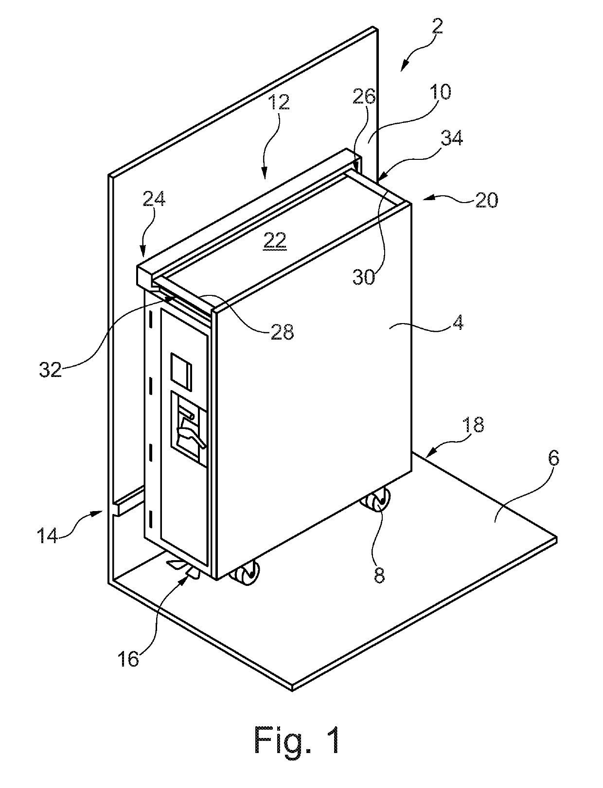
FIG. 1 shows an arrangement 2 for selectively arresting a serving trolley 4 in a three-dimensional, simplified view. Here, a horizontal ground surface 6 as a part of a cabin floor is shown, on which the serving trolley 4 stands with its wheels 8. Exemplarily, also a walling 10 that runs perpendicular to the ground surface 6 is shown here, at which the serving trolley substantially nes...


PUM


Abstract

An arrangement for selectively arresting a serving trolley in a cabin includes a walling extending perpendicularly to a cabin floor. The walling has a height at least equal to the height of a serving trolley. The arrangement has an upper arresting unit positioned at an upper fastening section of the walling and a lower arresting unit positioned at a lower fastening section of the walling. The upper arresting unit has a first engagement element and a second engagement element, wherein at least one of the engagement elements is movable relative to the other engagement element. The upper arresting unit releasably engages two distanced recesses at an upper end of the serving trolley by way of the engagement elements. The lower arresting unit includes at least one third engagement element and is designed for engaging a bottom side component of the serving trolley by way of the third engagement element.

Description

CROSS-REFERENCE TO RELATED APPLICATIONThis application claims the benefit of, and priority to, German patent application number DE 102016109722-5, filed May 25, 2016.TECHNICAL FIELDEmbodiments of the invention relate to an arrangement for selectively arresting a serving trolley in a cabin of a transportation system, in particular a cabin of a commercial aircraft. An embodiment of the invention further relates to a transportation system having a cabin created therein as well as an arrangement for selectively arresting a serving trolley in the cabin.BACKGROUNDIn the design of passenger cabins for transport systems, in particular for commercial aircraft, a challenge lies in maximizing the number of accommodatable passenger seats in the cabin with a constant volume of the space and maintained or improved comfort. Seats for vehicle attendants as well as galleys and toilets, which are provided for all persons, limit the available space for passenger seats. Concepts and design variants are...

Claims


Application Information

Patent Timeline
Patent Type & Authority Patents(United States)
IPC IPC(8): B64D11/04B64D11/00
CPCB64D11/0007B64D11/04Y02T50/46Y02T50/40
Inventor HEIDTMANN, ANDREASLANGE, ROLANDJENSEN, LASSE
Owner AIRBUS OPERATIONS GMBH
Why Eureka
Try Eureka