Stiffening of the connection between flaps in a nozzle of variable cross section

a technology of cross-section nozzle and connection, which is applied in the direction of machines/engines, climate sustainability, sustainable transportation, etc., can solve the problems of high static indeterminacy in the nozzle, asymmetry in the mechanical loading of the nozzle, and high wear of the moving parts of the lever control device, so as to improve the balancing of forces, improve the effect of taking up and good flexibility

Active Publication Date: 2020-03-03
SAFRAN CERAMICS SA +1
View PDF5 Cites 0 Cited by
  • Summary
  • Abstract
  • Description
  • Claims
  • Application Information

AI Technical Summary

Benefits of technology

[0008]By means of the rigid movement transmission part, it is possible to stiffen the connection between two adjacent levers and to transmit a movement force from a single actuator to both of these levers in a manner that is balanced and synchronized. This improves the balancing of the forces transmitted to the flaps and also improves taking up of the forces to which the flaps might be subjected, but without increasing the number of actuators, thereby making it possible to conserve a satisfactory overall weight for the nozzle.
[0009]Also, since the rigid movement transmission parts are mechanically independent of one another, the flap control device as a whole presents good flexibility, which is advantageous, in particular during thermal expansions in the nozzle.
[0012]This structure for the hinged connection compensates for tangential expansion of the ejection casing without impeding the transmission of movement forces as transmitted by each actuator to the flaps. This reduces the static indeterminacy of the flap control device.

Problems solved by technology

Although that solution enables the variable section nozzle to be made lighter in weight by minimizing the number of actuators in the nozzle, it leads to asymmetry in the mechanical loading of the nozzle.
This mechanical unbalance leads to a high level of static indeterminacy in the nozzle, to a linkage that is loaded tangentially, and to a high level of wear of the moving parts of the lever control devices.

Method used


Image

  • Stiffening of the connection between flaps in a nozzle of variable cross section
  • Stiffening of the connection between flaps in a nozzle of variable cross section
  • Stiffening of the connection between flaps in a nozzle of variable cross section

Examples


Embodiment Construction

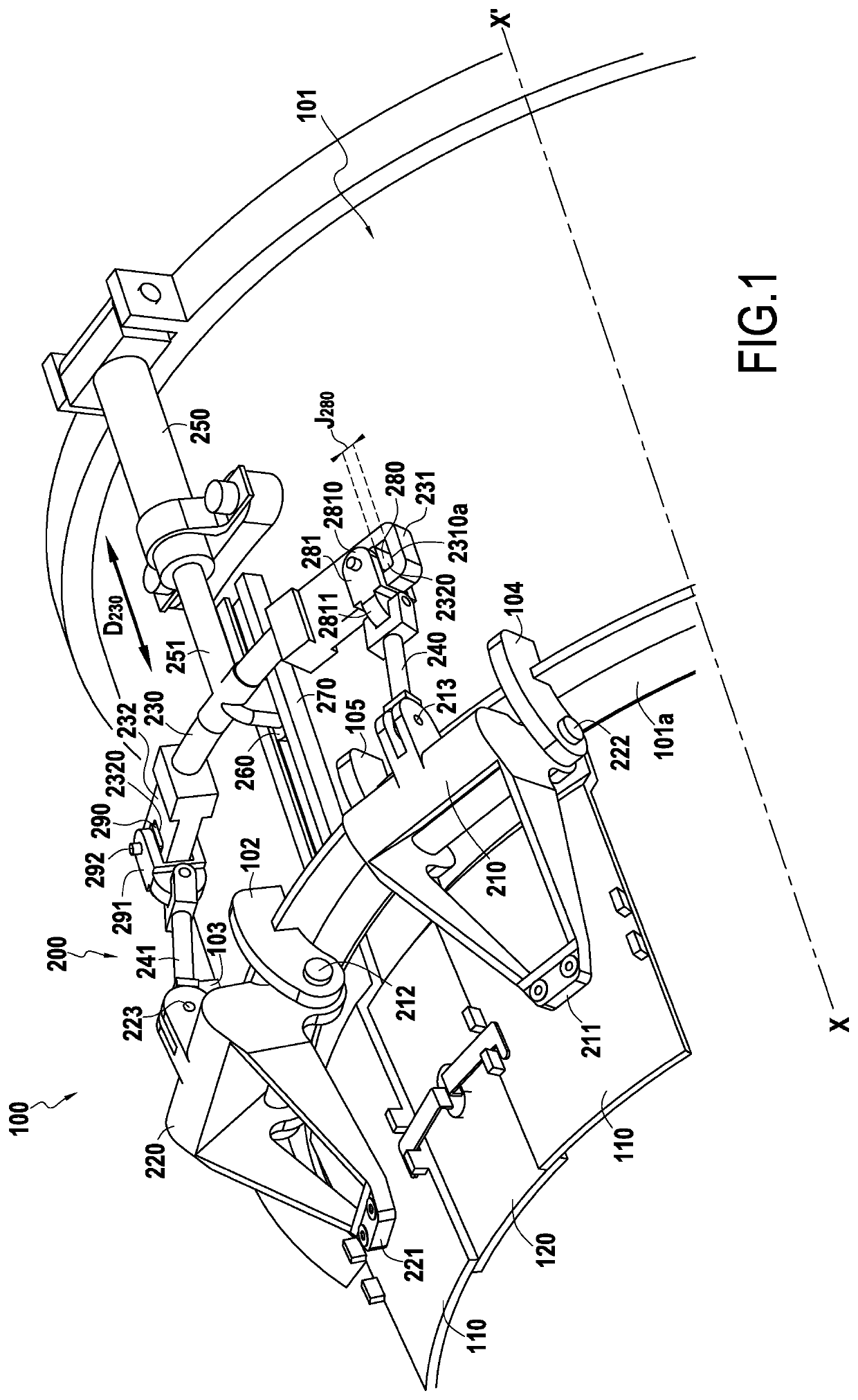
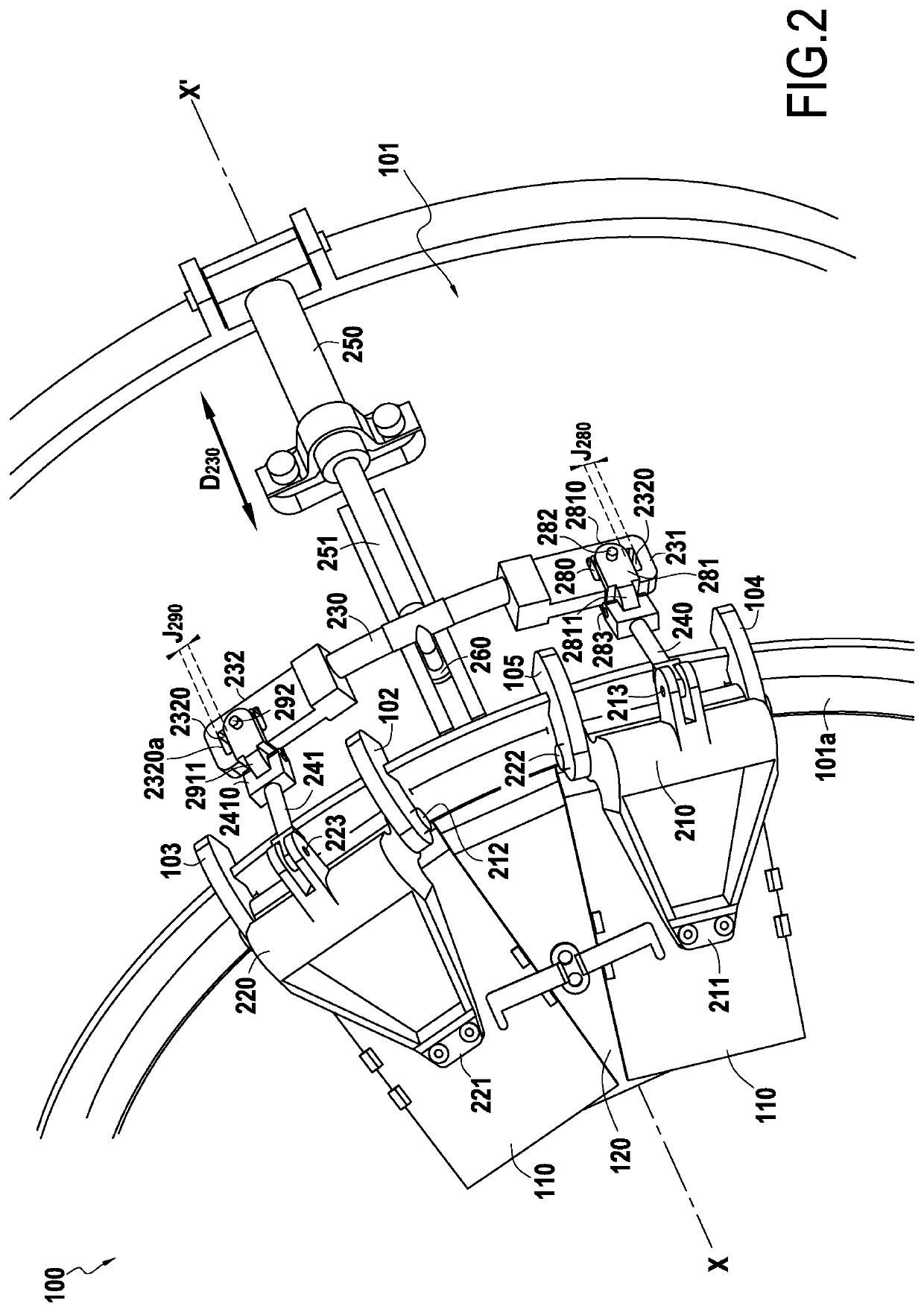
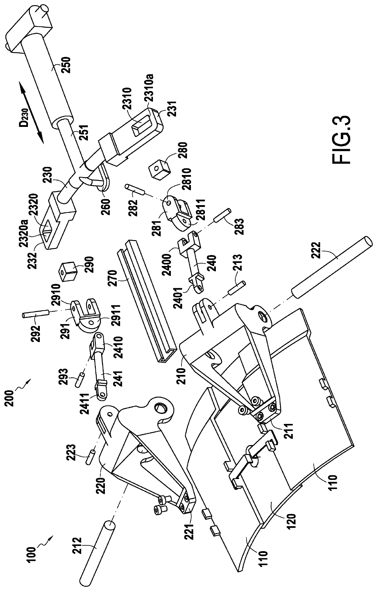
[0020]FIGS. 1 to 3 show a variable section nozzle 100 in an embodiment of the invention. The nozzle 100 comprises a series of internal movable flaps or “hot” flaps 110, and a control device 200 connected to two adjacent internal flaps 110, with the control device 200 being fastened on the ejection casing 101 of the nozzle 100. A sealing plate 120 is fastened between the internal flaps. Since FIGS. 1 and 2 are fragmentary views of the nozzle 100, only two adjacent internal flaps 110 and one control device 200 are shown in these figures. Naturally, the nozzle is made up of a ring of internal flaps 110 with a plurality of control devices 200 distributed in annular manner around the outside wall of the ejection casing 101.

[0021]Each internal flap 110 is connected to the ejection casing 101 by a movable lever 210 or 220 of the control device 200, each lever being pivotally mounted to the downstream end 101a of the ejection casing 101. Each internal flap 110 is movable between a first pos...


PUM


Abstract

A variable section nozzle includes an ejection casing and a plurality of internal flaps arranged in a ring downstream from the ejection casing. Each internal flap is connected to the ejection casing by a movable lever pivotally mounted to the downstream end of the ejection casing. Each lever is movable between a first position in which the internal flaps are in a high position and a second position in which the internal flaps are in a folded-down position. The nozzle includes a plurality of rigid movement transmission parts distributed circumferentially around the ejection casing. Each rigid movement transmission part is connected to two adjacent levers by connecting rods, and to a control actuator. Each rigid movement transmission part can move in a direction corresponding to the axial direction of the nozzle under the action of the control actuator to move the adjacent levers between the first and second positions.

Description

BACKGROUND OF THE INVENTION[0001]The invention relates to aeroengines fitted with a variable section nozzle, and more particularly to the connection that enables actuating movements to be transmitted to each flap.[0002]Document U.S. Pat. No. 7,533,533 describes a variable section nozzle having a plurality of internal flaps or “hot flaps” channeling the primary or main air stream of the engine. The internal flaps are actuated by control levers so as to modify the profile of the primary stream from the turbine engine (i.e. the ejection section(s) depending on whether the nozzle is merely a converging nozzle or a converging and diverging nozzle).[0003]In Document U.S. Pat. No. 7,533,533, only every other internal flap is controlled directly by an actuator that is connected to the control lever of the flaps. The flap adjacent to the flap fitted with an actuator is drivingly coupled by connection clevises that transmit a fraction of the force produced by the actuator to the coupled flap....

Claims


Application Information

Patent Timeline
Patent Type & Authority Patents(United States)
IPC IPC(8): F02K1/12F02K1/80
CPCF02K1/80F02K1/1253F02K1/1207F05D2240/40F05D2220/323F05D2240/90F02K1/15F05D2260/50Y02T50/60
Inventor LEPRETRE, GILLESTRAN, JULIEN
Owner SAFRAN CERAMICS SA
Why Eureka
Try Eureka