A segmental beam spreader

A segmental beam and spreader technology, which is applied in the direction of load hanging components, transportation and packaging, etc., can solve the problems of not being able to meet the needs of use, large swing range of segmental beams, unbalanced force of segmental beams, etc., and achieve strong practicability , Reasonable structural design, improve the effect of force balance

Active Publication Date: 2022-01-28
THE 4TH ENG CO LTD OF CHINA RAILWAY 16TH BUREAU GRP CO LTD
View PDF10 Cites 0 Cited by
  • Summary
  • Abstract
  • Description
  • Claims
  • Application Information

AI Technical Summary

Problems solved by technology

[0003] In the construction industry, the existing segmental beam hoist is usually equipped with a single bracket to lift the segmental beam. Although it is simple to use, the segmental beam is prone to unbalanced force during the hoisting process of the segmental beam. phenomenon, resulting in a large swing of the segmental beam during the lifting process
In addition, for some huge segmental beams, the spreaders in the prior art obviously cannot meet the needs of use

Method used


Image

  • A segmental beam spreader
  • A segmental beam spreader
  • A segmental beam spreader

Examples


Embodiment 1

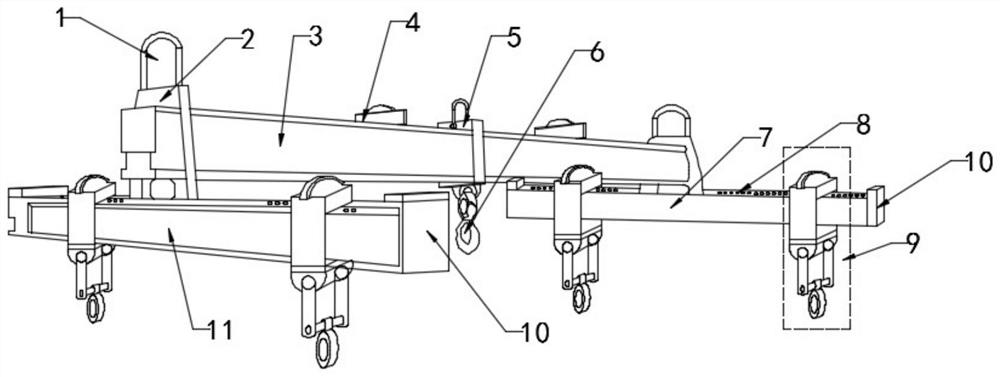
[0026] see figure 1 , In Embodiment 1 of the present invention, a segment beam hanger includes: a cross frame 3, a first bracket 7 and a second bracket 11; the upper end of the first bracket 7 and the upper end of the second bracket 11 are welded and fixed with The first fixing block 2 is integrally formed with the second bracket 11 , and the first fixing block 2 and the first bracket 7 are integrally formed; the upper end of the second bracket 11 is connected with the horizontal frame 3 through the first fixing block 2 Fixed, the upper end of the first bracket 7 is connected and fixed with the horizontal frame 3 through the first fixing block 2;

[0027] A second fixing block 5 is arranged in the middle of the horizontal frame 3, a pull ring 1 is arranged on the upper end of the second fixing block 5, and a first hook 6 is arranged at the lower end of the second fixing block 5; Blocks 10 are provided on the left and right sides of the two brackets 11 , and the first bracket ...

Embodiment 2

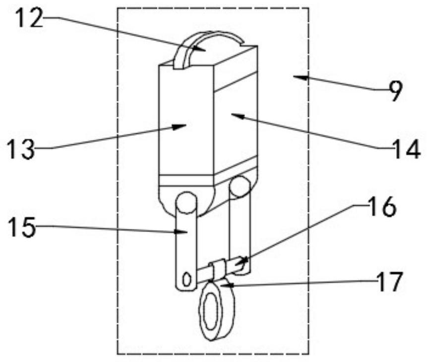
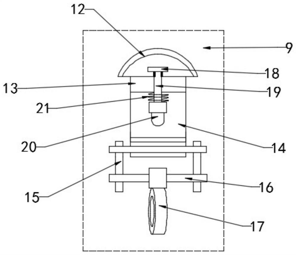
[0034] see image 3 , further, a limit assembly is provided inside the opening channel 14 of the stretching assembly 9, and the limit assembly includes a pull handle 18, a connecting rod 19 and an insertion end 20, and the upper end of the connecting rod 19 passes through the slider 13. The end part is provided with a pull handle 18, the lower end of the connecting rod 19 passes through the slider 13 and then extends into the opening channel 14, and the bottom end of the connecting rod 19 is provided with an insertion end 20;

[0035] Specifically, a compression spring 21 is installed on the portion of the connecting rod 19 between the insertion end 20 and the inner wall of the slider 13;

[0036] When the stretching assembly 9 slides on the first bracket 7 or the second bracket 11 and needs to be limited by the limiting assembly, after the stretching assembly 9 slides on the first bracket 7 or the second bracket 11 to an appropriate position, The insertion end 20 automatical...


PUM


Abstract

The invention relates to the technical field of segmental beam hangers, and specifically discloses a segmental beam hanger, which includes a horizontal frame, a first bracket, and a second bracket; The upper end is provided with a pull ring, and the lower end of the second fixed block is provided with a first hook; the upper end of the first bracket and the upper end of the second bracket are welded and fixed with the first fixed block; the first bracket and the second bracket are equipped with There are tensile components; the structural design of the segmental beam spreader is reasonable. When the segmental beam needs to be hoisted, the rope is wound on the segmental beam, and then the tensile component on the first bracket and the second bracket The stretching assembly on the top and the first hook at the lower end of the second fixed block stretch the rope at the same time, and finally the horizontal frame is stretched by the hoisting machine, and then the segmental beam is hoisted; since there are multiple stretching points for the rope , thereby improving the force balance of the segmental beam during the hoisting process and the stability when it is raised.

Description

technical field [0001] The invention relates to the technical field of a segment beam spreader, in particular to a segment beam spreader. Background technique [0002] A spreader is a device that lifts heavy objects in a hoisting machine. The most commonly used slings for lifting finished items are slings, slings, and others include slings, lifting suction cups, clamps and forks. Spreaders are widely used in the lifting and hoisting industry, especially in the construction of high-rise buildings. [0003] In the construction industry, the existing segment beam spreaders are usually equipped with a single bracket to hoist the segment beams. Although the use is simple, the segment beams are prone to unbalanced forces during the segment beam hoisting process. phenomenon, resulting in a large swing of the segment beam during the lifting process. In addition, for some bulky segment beams, the spreader in the prior art obviously cannot meet the usage requirements. [0004] In ...

Claims


Application Information

Patent Timeline
Patent Type & Authority Patents(China)
IPC IPC(8): B66C1/12
CPCB66C1/12
Inventor 王跃东闫红强张存兴李征何佩军盖健卫张岳飞
Owner THE 4TH ENG CO LTD OF CHINA RAILWAY 16TH BUREAU GRP CO LTD
Why Eureka
Try Eureka