A double-supported submersible thruster

A submersible flow propeller, a mounted technology, applied in water aeration, chemical instruments and methods, biological water/sewage treatment, etc., can solve the problems of low mechanical efficiency, no positioning and clamping mechanism, and large market consumption.

Active Publication Date: 2016-05-18
亚太泵阀有限公司
View PDF3 Cites 0 Cited by
  • Summary
  • Abstract
  • Description
  • Claims
  • Application Information

AI Technical Summary

Problems solved by technology

Due to the high technical content and high import rate of this equipment, it has a great influence on the sewage treatment and discharge, and the market usage is large
Conventional submersible flowmaker equipment includes submersible flowmaker host, lifting device, underwater single guide rail, underwater support frame (generally a flat or circular tube structure), and its underwater part structure is a single-rod support connection auxiliary Support frame type, the pulley mechanism of the main engine of the flow booster is set at the tail. The conventional installation is that the flow booster is lifted by the lifting device, and the flow booster slides down along the underwater single guide rail through the tail pulley mechanism, and slides to the support at the lower end of the guide rail. The submersible thruster with this structure has the following three defects: one is that the underwater support frame has no positioning and clamping mechanism, and its stability is poor. The sliding gap connection between the flow boosters, the support frame bears the gravity of the flow booster, and the positioning, fixing and clamping of the flow booster cannot be realized, and the vibration and impact of the submersible flow booster cannot be overcome. Short and low mechanical efficiency; second, the main engine tail wing pulley mechanism is four sets of pulleys, which hug the single slide rail two by two, which is easy to form self-locking, causing slipping and jamming; Eccentric moment, aggravating vibration and noise
According to the above analysis, the support placement structure of the traditional conventional submersible flow booster is unreasonable, and the sliding mechanism on the main engine is unscientific. It is urgent to solve these technical problems

Method used


Image

  • A double-supported submersible thruster
  • A double-supported submersible thruster
  • A double-supported submersible thruster

Examples


Embodiment Construction

[0034] Embodiments of the present invention will be further described below in conjunction with the accompanying drawings.

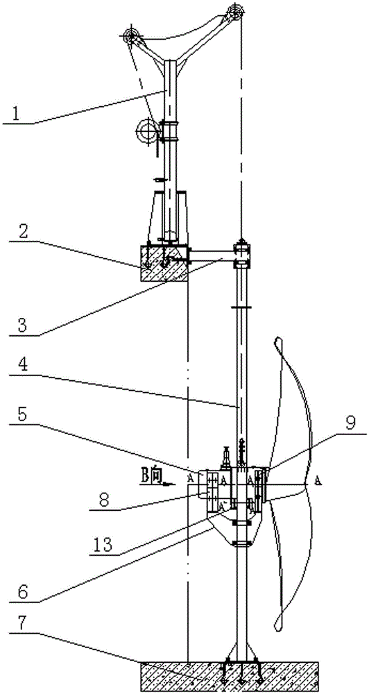
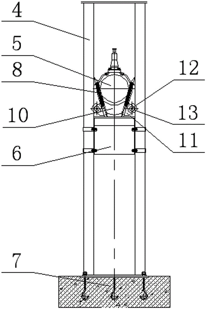
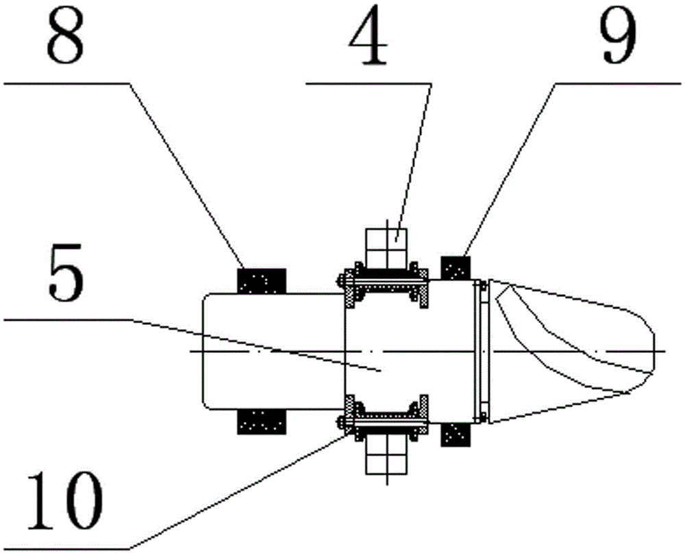
[0035] Figure 1-2 As shown, a double-supported submersible flowmaker, which includes a lifting device 1, a pool surface installation foundation 2, a connecting rod 3, two supporting slide rails 4, a submersible flowmaker main body 5, a placement seat 6 and a pool bottom The installation base 7, the lifting device 1 is fixedly installed on the pool surface installation base 2, the bottom of the two supporting slide rails 4 is fixedly installed on the pool bottom installation base 7, the upper part is fixedly connected with the right end of the connecting rod 3, and the left end of the connecting rod 3 is connected with the pool surface The installation base 2 is fixedly connected, the placement seat 6 is fixedly installed between two support slide rails 7, the submersible flow booster 5 is coupled in the placement seat 6, and the two support slide rails ...


PUM


Abstract

The invention relates to a double-supported submersible water impeller comprising a submersible water impeller main body, a lifting device and two supporting sliding rails, wherein the lifting device is fixed on the surface of a pool through a pool surface mounting foundation; the two supporting sliding rails are vertically fixed at the bottom of the pool through a pool bottom mounting foundation; the top ends of the two supporting sliding rails are pulled and connected to the pool surface mounting foundation through connecting rods; mounting seats are penetrated and fixed on the two supporting sliding rails and are provided with two brackets back and forth along the direction vertical to the direction of the supporting sliding rails; and the submersible water impeller main body is hung and connected to the lifting device through a steel wire rope and is in a state of being respectively supported on the two brackets after lifting along the vertical direction of the supporting sliding rails or falling to the front and rear ends of the axial direction of the submersible water impeller main body. By using the double-supported submersible water impeller, the technical problems of high underwater vibration, high noise and short service life of an impeller are thoroughly solved; and the double-supported submersible water impeller is stable in working, reliable in operation and simple in maintenance.

Description

technical field [0001] The invention relates to a water vessel, in particular to a double-supported submersible thruster. Background technique [0002] In the sewage treatment industry, submersible flowmakers are widely used in anaerobic pools, anoxic pools and aeration tanks. Generally, the depth of the pool is about 5 meters, and the submersible flowmakers normally work at a position of 1.5 meters underwater. Stir sludge, promote the flow of water medium, maintain the flow velocity at the bottom of the pool ≥ 0.3m / s, prevent sludge settlement, and improve the efficiency of sewage treatment. Due to the high technical content and high import rate of this equipment, it has a great influence on the sewage treatment and discharge, and the market usage is relatively large. Conventional submersible flowmaker equipment includes submersible flowmaker host, lifting device, underwater single guide rail, underwater support frame (generally a flat or circular tube structure), and its ...

Claims


Application Information

Patent Timeline
Patent Type & Authority Patents(China)
IPC IPC(8): C02F3/00C02F7/00
CPCC02F3/00C02F3/1284C02F3/28C02F2203/00Y02W10/10
Inventor 梅红霖张成华黄岭
Owner 亚太泵阀有限公司
Why Eureka
Try Eureka