Rotating electric machine
a technology of rotating electric machines and rotating shafts, applied in the direction of electronic commutators, dynamo-electric converter control, magnetic circuit shape/form/construction, etc., can solve the problems of external disturbance of pulse voltage and noise generation, and achieve the effect of improving force balan
- Summary
- Abstract
- Description
- Claims
- Application Information
AI Technical Summary
Benefits of technology
Problems solved by technology
Method used
Image
Examples
first exemplary embodiment
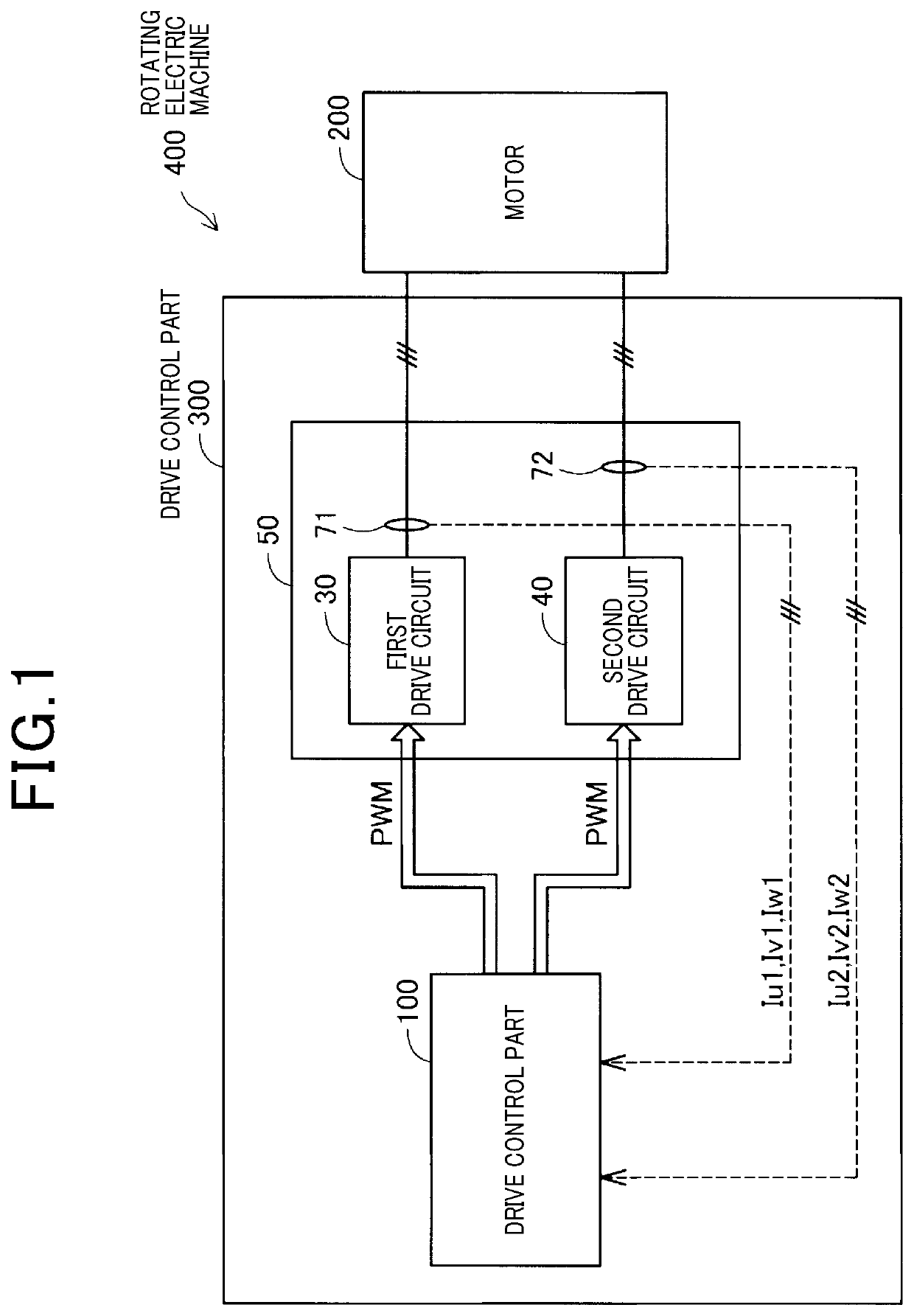
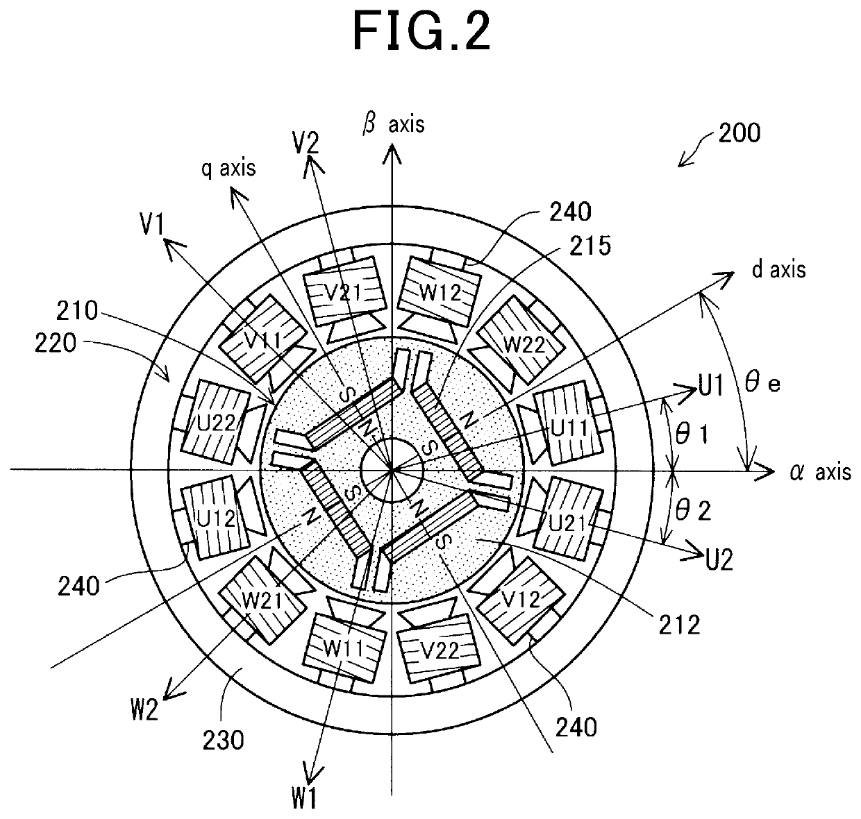
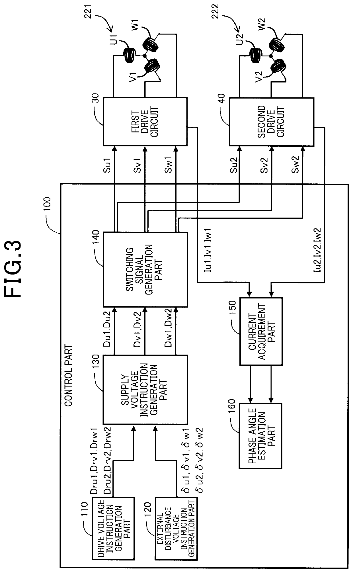
[0042]A description will be given of the rotating electric machine 400 according to a first exemplary embodiment of the present invention with reference to FIG. 1 to FIG. 10A, FIG. 10B and FIG. 10C.
[0043]FIG. 1 is a view showing a structure of the rotating electric machine 400 according to the first exemplary embodiment of the present invention. As shown in FIG. 1, the rotating electric machine 400 according to the first exemplary embodiment has a motor 200 and a drive control part 300.
[0044]The drive control part 300 has a motor drive unit 50 and a control part 100. The motor 200 in the first exemplary embodiment is a synchronous motor with a permanent magnet type or a permanent magnet synchronous motor.
[0045]The motor drive unit 50 has a first drive circuit 30 and a second drive circuit 40. The first drive circuit 30 and the second drive circuit 40 drive dual three phase windings of a stator 220 in the motor 200.
[0046]The control part 200 generates pulse width modulation (PWM) sig...
second exemplary embodiment
[0141]A description will be given of the rotating electric machine according to the second exemplary embodiment with reference to FIG. 11. FIG. 11 is a timing chart showing a relationship between adjusted supply voltage instruction signals and the PWM comparison wave CW to be used in the rotating electric machine according to the second exemplary embodiment of the present invention.
[0142]As shown in FIG. 11, in the structure of the rotating electric machine according to the second exemplary embodiment, the adjustment part 132 adjusts the supply voltage instruction signals Du1, Dv1 and Dw1 to the adjusted supply voltage instruction signals Du1*, Dv1* and Dw1*, to be used for the first coil 221 so that the maximum supply voltage instruction signal therein is equal to the maximum PWM comparison wave CW in each PWM period T while maintaining the voltage level difference between the supply voltage instruction signals Du1, Dv1 and Dw1 before the level adjustment.
[0143]Similarly, the adjus...
third exemplary embodiment
[0146]A description will be given of the rotating electric machine according to the third exemplary embodiment with reference to FIG. 12. FIG. 12 is a timing chart showing a relationship between adjusted supply voltage instruction signals and the PWM comparison wave CW to be used in the rotating electric machine according to the third exemplary embodiment of the present invention.
[0147]As shown in FIG. 12, in the structure of the rotating electric machine according to the third exemplary embodiment, the adjustment part 132 (see FIG. 5) adjusts the supply voltage instruction signals Du1, Dv1 and Dw1 to the adjusted supply voltage instruction signals Du1*, Dv1* and Dw1*, respectively to be used for the first coil 221 so that the minimum supply voltage instruction signal therein is equal to a predetermined voltage level Lref between the maximum PWM comparison wave CW and the minimum PWM comparison wave CW in each PWM period T while maintaining the supply voltage instruction signals Du1...
PUM
 Abstract
Description
Claims
Application Information
 - R&D
- Intellectual Property
- Life Sciences
- Materials
- Tech Scout
- Unparalleled Data Quality
- Higher Quality Content
- 60% Fewer Hallucinations
Browse by: Latest US Patents, China's latest patents, Technical Efficacy Thesaurus, Application Domain, Technology Topic, Popular Technical Reports.
© 2025 PatSnap. All rights reserved.Legal|Privacy policy|Modern Slavery Act Transparency Statement|Sitemap|About US| Contact US: help@patsnap.com


