
Positioning arrangement

a positioning arrangement and positioning device technology, applied in the direction of positioning apparatus, metal-working machine components, manufacturing tools, etc., can solve the problem that the stationary part of the positioning device cannot move freely relative to the base element, and achieve the effect of low spring constant and low restoring for

Active Publication Date: 2020-03-03
SCHNEEBERGER HLDG AG
View PDF17 Cites 1 Cited by
  • Summary
  • Abstract
  • Description
  • Claims
  • Application Information

AI Technical Summary

Benefits of technology

The patent text describes a workpiece positioning arrangement for processing, machining, lighting, and inspecting semiconductor structures, microstructures, nanostructures, and wafers. The arrangement includes a carrier element and a base element, with a zero position means to bring the carrier element into a defined position relative to the base element. The zero position means can be actively or passively activated, and can involve springs or slanted surfaces. The arrangement also includes a workpiece processing device, such as a machining or inspection device, which is preferably fixedly mechanically coupled to the carrier element. The structural design of the arrangement prevents actuator-induced eigenvibrations and allows for efficient workpiece positioning. The technical effects of this arrangement include improved accuracy and efficiency in processing and inspection of semiconductor structures, microstructures, nanostructures, and wafers.

Problems solved by technology

However, the stationary part of the positioning device would be stationary if the decoupling device were turned off, for example, so that the carrier element (and hence the stationary part of the positioning device) can no longer move freely relative to the base element (for example, deactivating a pump for any fluid film storage devices and the like, if any are present).

Method used


Image

  • Positioning arrangement
  • Positioning arrangement
  • Positioning arrangement

Examples


Embodiment Construction

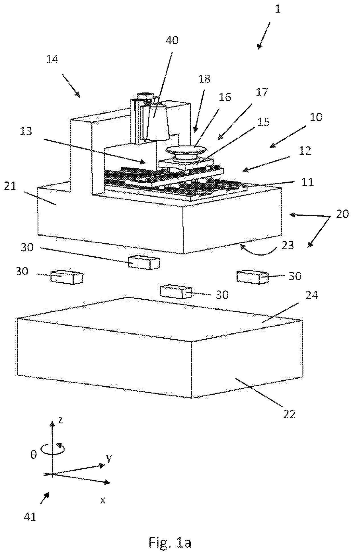
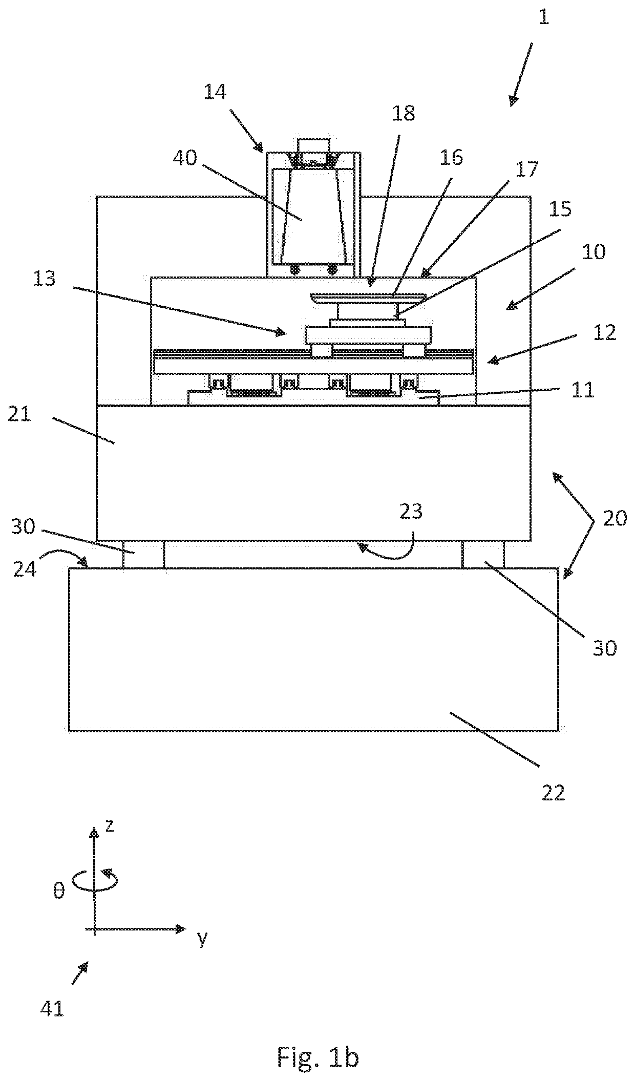
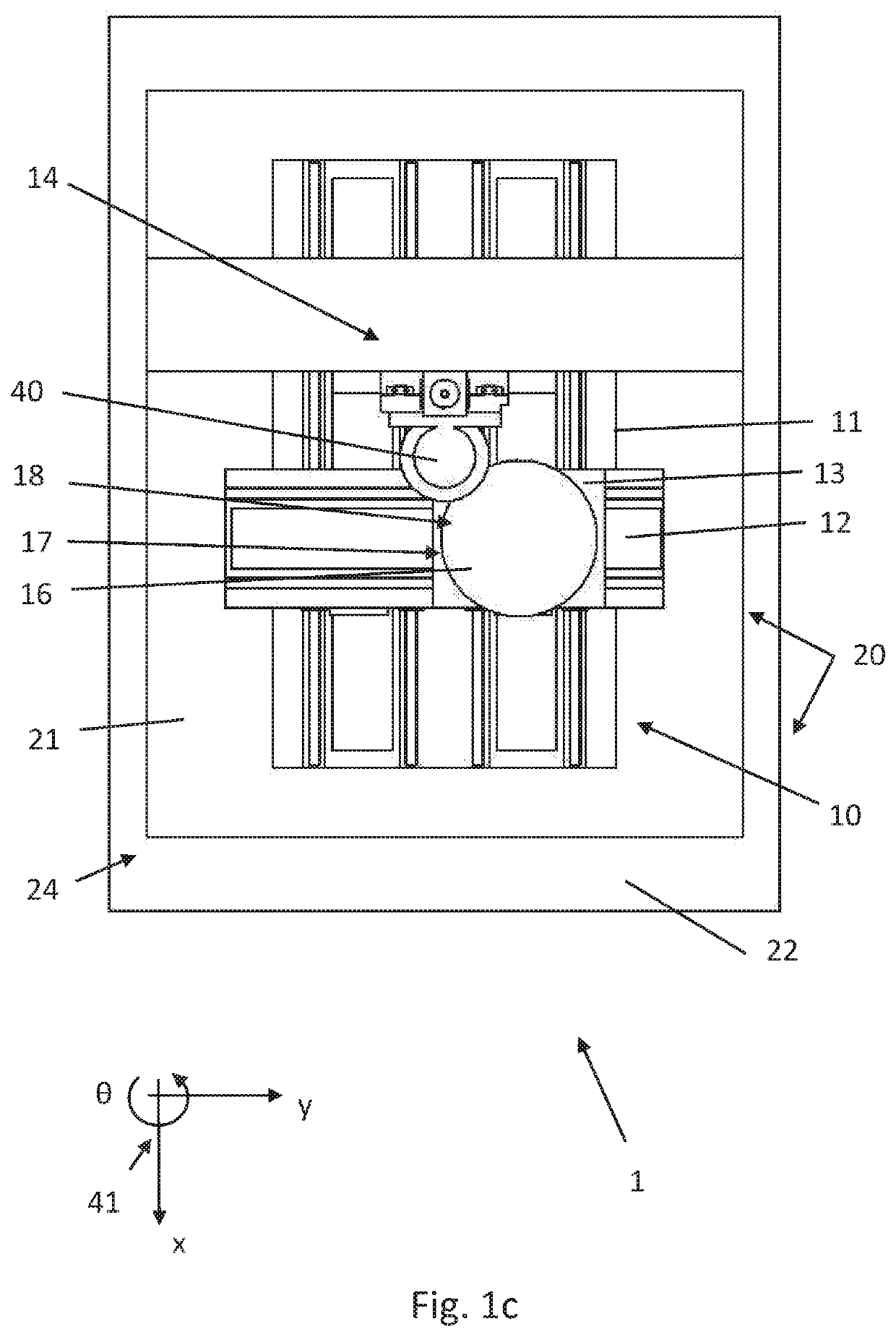
[0035]Shown on FIG. 1a-1c is a schematic exploded view of a first possible exemplary embodiment for a processing table 1, for example for semiconductor microstructures or other workpieces.

[0036]Actual processing is accomplished with the positioning table 10, which in terms of its basic structural design essentially corresponds to a positioning table of the kind common in prior art and also industrially widely used. The positioning table 10 comprises a pedestal 21, which usually has a comparatively large mass. The pedestal 21 is used to secure the “actually” stationary plate 11 of the positioning table 10, for example which comprises guide rails or travel rails for a movable carriage. The pedestal 21 also has mechanically fixedly secured thereto a support arm 14, on which a processing head 40 is in turn mechanically fixedly secured. As a consequence, the pedestal 21, support arm 14, processing head 40 and stationary plate 11 of the positioning table 10 are mechanically coupled togeth...


PUM


Abstract

A workpiece positioning arrangement comprises a positioning device for positioning a workpiece as well as a decoupling device for the decoupled storage of the positioning device, wherein the decoupling device comprises a carrier element, on which the positioning device is arranged, and a base element, on which the carrier element is supported. For decoupling the dynamic reaction forces of the positioning device on the base element, the carrier element is supported on the base element so as to move freely at least in a certain range, preferably essentially free of counterforces, in a sliding manner.

Description

BACKGROUND OF THE INVENTION[0001]1. Field of the Invention[0002]The invention relates to a workpiece positioning arrangement, which comprises a positioning device for positioning a workpiece as well as a decoupling device for the decoupled storage of the positioning device, wherein the decoupling device comprises a carrier element, on which the positioning device is arranged, and a base element, on which the carrier element is supported.[0003]2. Background[0004]In many fields of technology, workpieces to be machined are machined or already machined workpieces are inspected with the help of machining devices or inspection machines (or more generally: a processing system), in which a tool head or inspection head is moved relative to the workpiece to be machined or inspected. For purposes of machining or inspecting (or more generally: processing), the tool head / inspection head is here either moved by corresponding actuators, or the workpiece is moved by actuators in a movably arranged ...

Claims


Application Information

Patent Timeline
Patent Type & Authority Patents(United States)
IPC IPC(8): H01L21/68B23Q1/38B23Q1/01B23Q11/00H01L21/687
CPCB23Q11/0032B23Q1/015H01L21/68H01L21/68757B23Q1/38B23Q3/02H01L21/68785
Inventor VIX, MARTIN
Owner SCHNEEBERGER HLDG AG
Learn More