Transmitter, transmission method, and receiver based on time-domain windows

a transmission method and time-domain technology, applied in the field of transmission methods, transmitters, receivers, etc., can solve the problems of high electric power out of band radiation (i.e., out of band emission), complex transmission symbol generating process, and high electric power consumption efficiency. achieve the effect of efficient generation of transmission signals

Active Publication Date: 2020-03-03
KYOTO UNIV
View PDF15 Cites 2 Cited by
  • Summary
  • Abstract
  • Description
  • Claims
  • Application Information

AI Technical Summary

Benefits of technology

[0030]In the channel aggregation in which a plurality of channels are bound and transmitted, in the case where the transmission is performed in the channels whose frequencies are away from each other or in the case where the conditions such as a spectrum mask, transport electric power, bandwidth, and the like which are required in the channels to be bound are different, it is difficult to efficiently generate the transmission signal. According to at least one embodiment, the invention can generate in a lump the transmission signals which satisfy the transmitting conditions in each channel. The effects disclosed here are not always limited but may be any one of the effects disclosed in the invention. The contents of the invention are not limitedly interpreted by the effects shown as examples in the following description.

Problems solved by technology

Although the OFDM(A) largely contributes to improvement of the transmission capacity of the communication system owing to its high frequency use efficiency, out-of-band radiation electric power (i.e., out-of-band emission) is high and there is a problem about an electric power consumption efficiency.
According to those LPFs, since a filter length in a time-domain varies in dependence on design conditions, in order to satisfy a time-domain signal length decided by a certain system format, a transmission symbol generating process becomes complicated or difficult.

Method used


Image

  • Transmitter, transmission method, and receiver based on time-domain windows
  • Transmitter, transmission method, and receiver based on time-domain windows
  • Transmitter, transmission method, and receiver based on time-domain windows

Examples


Embodiment Construction

[0040]Embodiments of the invention will be described hereinbelow. The embodiments which will be described hereinbelow are exemplary specific examples of the invention and various kinds of limitations which are technically preferred are added. However, it is assumed that the scope of the invention is not limited to those embodiments unless otherwise described to limit the invention in the following explanation.

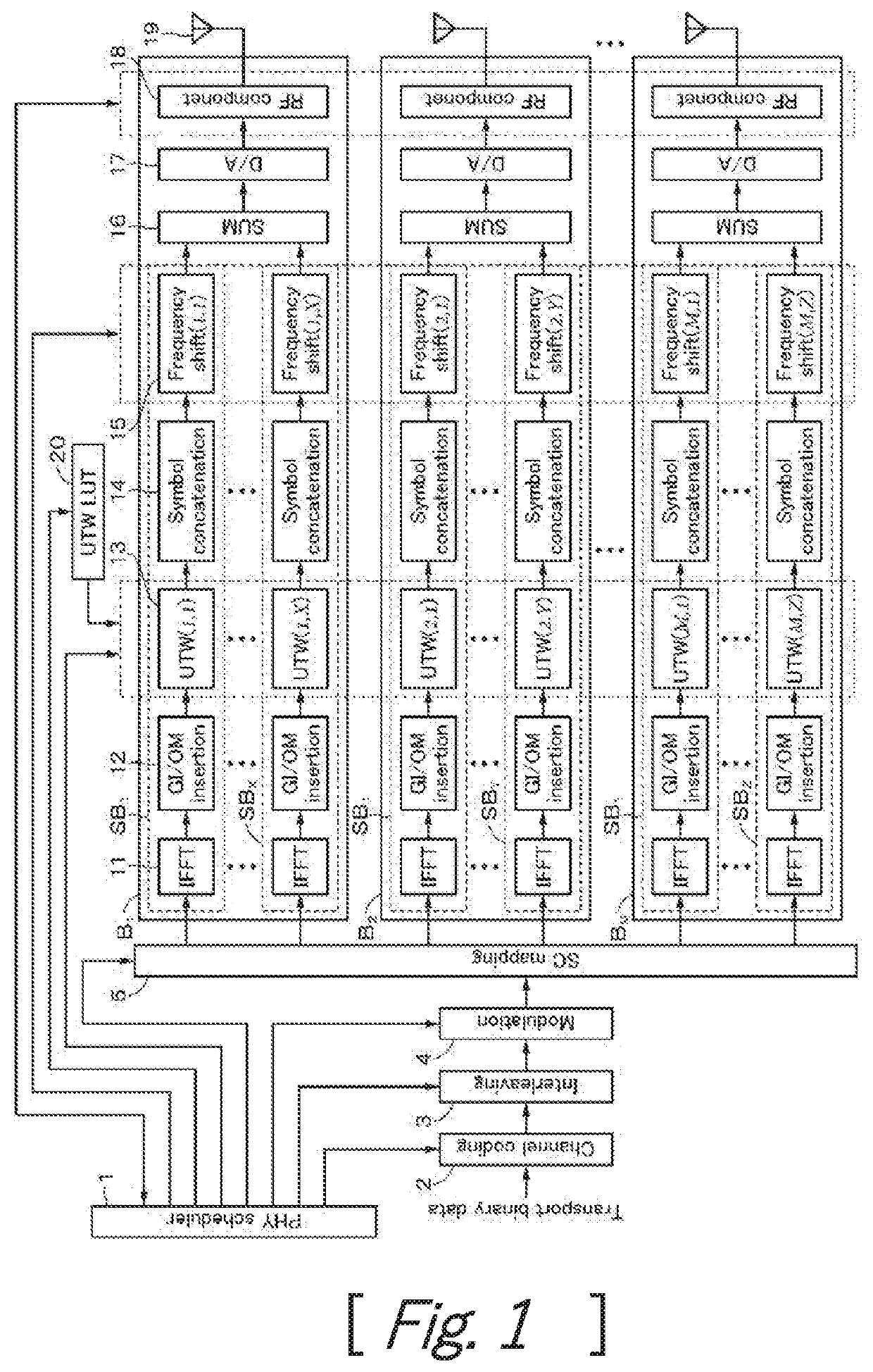
[0041]One embodiment is an OFDM signal transmitter for transmitting a signal of an OFDM system. That is, it is a transmitter for transmitting, every block, time-domain symbols like an OFDM or OFDMA which enables a transmission signal to be transmitted by an arbitrary frequency band, an arbitrary channel width, an arbitrary spectrum mask, and arbitrary electric power. FIG. 1 shows a construction of the embodiment of the invention.

[0042]Transport binary data is supplied to a channel coding unit 2 and is channel encoded. An output of the channel coding unit 2 is supplied to an int...


PUM


Abstract

A transmitter using a channel aggregation in which available channels existing in various frequency bands are bound and transmitted and using an Orthogonal Frequency Division Multiplexing (OFDM), an Orthogonal Frequency Division Multiple Access (OFDMA), or a system similar to them as a modulation system. One or a plurality of transmission units are provided in parallel, and one or a plurality of transmission processing units are provided in parallel. The transmission processing unit has an inverse fast Fourier transforming circuit or a discrete inverse Fourier transforming circuit, a GI and overlap margin (OM) insertion circuit, and a time-domain windowing processing unit. The time-domain windowing processing unit multiplies a universal time-domain window function in accordance with a spectrum mask and transport electric power which are required in each channel, thereby suppressing out-of-band radiation electric power every channel. A kind and a window transition duration of the time-domain window function can be arbitrarily set every channel.

Description

CROSS REFERENCE TO PRIOR APPLICATION[0001]This application is a National Stage Patent Application of PCT International Patent Application No. PCT / JP2016 / 005257 (filed on Dec. 28, 2016) under 35 U.S.C. § 371, which claims priority to Japanese Patent Application No. 2016-002695 (filed on Jan. 8, 2016), which are all hereby incorporated by reference in their entirety.TECHNICAL FIELD[0002]The present invention relates to a transmitter, a transmission method, and a receiver which can perform an efficient channel aggregation.BACKGROUND ART[0003]An attention is paid to such a channel aggregation that available channels existing in various frequency bands are bound and transmitted in order to increase a communication capacity. In a wireless LAN system such as IEEE802.11ac, a cellular system such as LTE-Advanced, a white space wireless system such as IEEE802.11af, a fifth generation mobile communication system (5G system), or the like, international standard specifications related to the cha...

Claims


Application Information

Patent Timeline
Patent Type & Authority Patents(United States)
IPC IPC(8): H04J11/00H04B1/00H04L27/26H04L25/03H04J1/00
CPCH04L27/2628H04B1/0064H04L25/03343H04L27/2656H04J1/00H04L25/03821H04J11/0023H04L25/03834H04L27/2626H04L27/26265H04L27/26412
Inventor MIZUTANI, KEIICHIHARADA, HIROSHI
Owner KYOTO UNIV
Why Eureka
Try Eureka