Acoustic and RF cancellation systems and methods

a technology of acoustic and rf, applied in the field of communication, acoustic and radio measurement, can solve the problems of inability to keep up with the changing environment of the wave, inability to optimal adapt to the wave environment, and difficulty in implementation

Active Publication Date: 2020-03-10
FOSTER-MILLER +1
View PDF13 Cites 2 Cited by
  • Summary
  • Abstract
  • Description
  • Claims
  • Application Information

AI Technical Summary

Benefits of technology

[0021]A method of employing a Kalman filter as the Filtered-X tuning mechanism was found to be ideal. This method allows us to describe the expected rate of change of the environment and the expected signal level for desired received signals. The system then automatically tunes itself at exactly the optimum rate. Several methods for reducing the complexity of the computations required are discussed and disclosed.
[0026]Preferably, this digital cancellation, which applies linear combinations of the time-shifted desired signal, the cancellation signal, and the amplifier signal works perfectly well even if there is no analog cancellation present (i.e. in situations where the front-end has sufficient dynamic range to capture the outbound signal and noise together).

Problems solved by technology

We found that the standard methods for adaptation were not optimal.
In slower systems, they might not be able to keep up with the changing environment of the waves.
Tweaking the adaptive rate may be possible but may be difficult to implement.
Digital cancellation in the Stanford system was required due to the limited analog cancellation.
As RF systems scale up in power, amplifier distortion models become less accurate meaning that the Judell system may fail in some instances to adequately cancel the real distortion terms.
Unfortunately, Class D amplifier distortion is large (sometimes as much as 10%) and is difficult to model accurately.

Method used


Image

  • Acoustic and RF cancellation systems and methods
  • Acoustic and RF cancellation systems and methods
  • Acoustic and RF cancellation systems and methods

Examples


Embodiment Construction

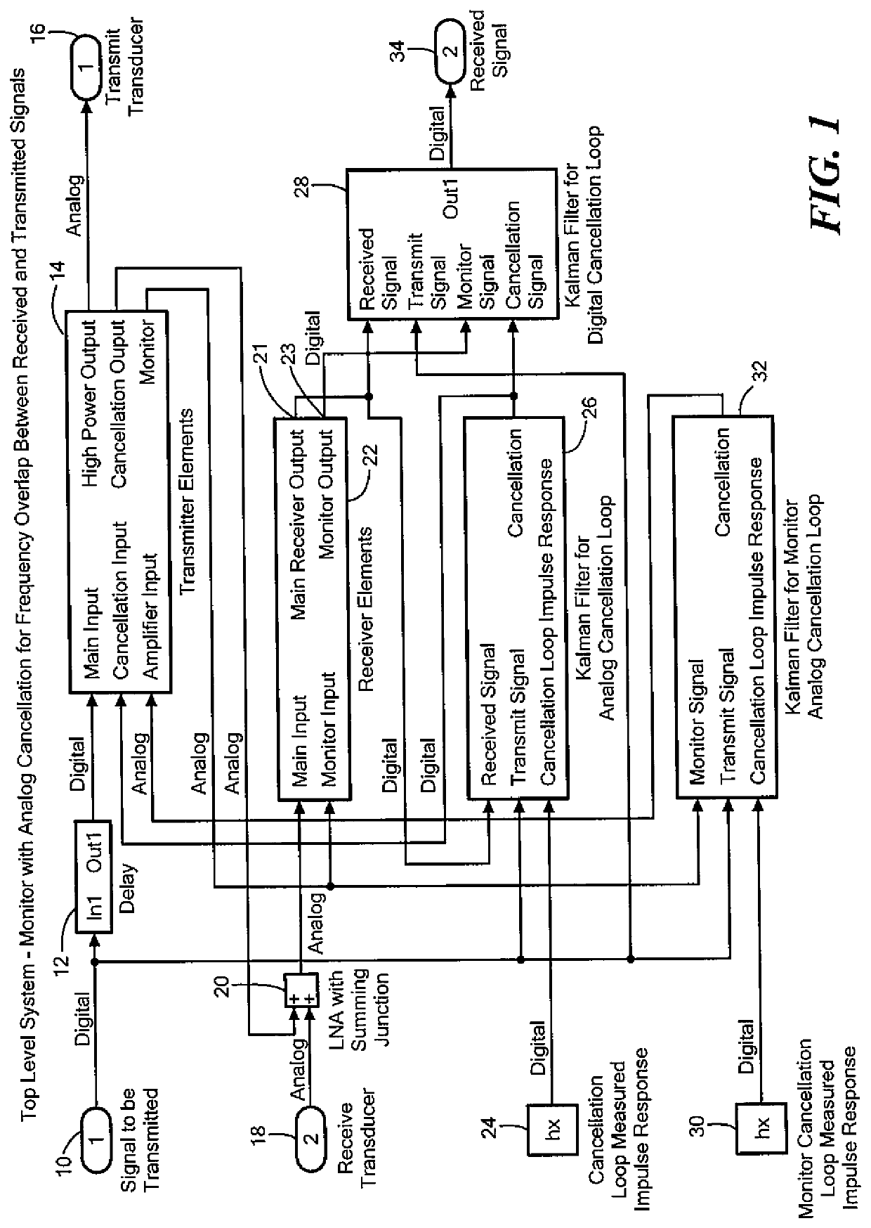
[0040]The exemplary circuitry of FIGS. 1-6 is described as follows. Signal input 10 is the digital signal for transmission. A blocking filter, which is optional, may include a digital filter that ensures that the signal to be transmitted contains no frequencies outside the ranges allocated for a particular system. The source may already be clean enough to omit this bock. Delay 12 provides for analog cancellation. See PCT / US2016 / 037243.

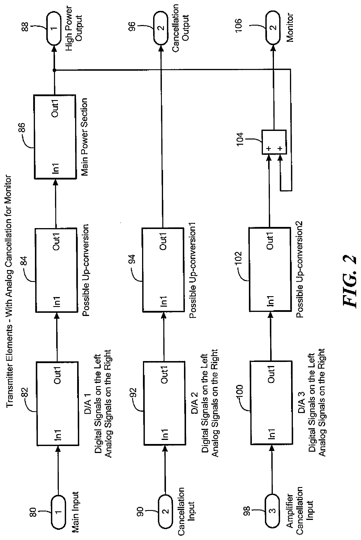
[0041]The transmitter elements 14 are the digital inputs for the main transmission and cancellation signals. These signals are converted to analog. Depending on frequency of use, there may be analog up-conversion (mixers). The high power output contains the appropriate amplifier and impedance matching to produce an analog output for the transmit transducer. High power typically means more than just carrying signal but this might still only be in the milliWatt region). Appropriate filtering and buffering are provided for the analog cancellation output. ...


PUM


Abstract

A method of performing cancellation for acoustic or electromagnetic measurement or communications includes receiving an output signal to be applied to a transmit transducer, introducing a delay to the output signal to produce a delayed output signal, applying the delayed output signal to the transmit transducer, receiving an input signal from a receiving transducer, wherein the input signal comprises at least a portion of the delayed output signal, and iteratively solving a Kalman filter problem as a function of the input signal, the output signal, and the delay to produce a first filtered input signal.

Description

RELATED APPLICATIONS[0001]This application claims benefit of and priority to U.S. Provisional Application Ser. No. 62 / 517,376 filed Jun. 9, 2017, under 35 U.S.C. §§ 119, 120, 363, 365, and 37 C.F.R. § 1.55 and § 1.78, which is incorporated herein by this reference.FIELD OF THE INVENTION[0002]The inventions herein are applicable to communications, acoustic and radio measurements.BACKGROUND OF THE INVENTION[0003]One problem in acoustic and radio frequency communication and measurement systems is receiving a low-level received signal in the presence of a high-level outbound transmitted signal. The outbound signal has a direct path from transmit to receive and may also include some indirect paths such as bouncing off walls, the surface of the ocean, etc. The overall rejection of the outbound signal needs to be around 100 dB for communications and 160-200 dB for some measurement systems.[0004]There are a number of possible techniques for solving these problems. These include isolation wh...

Claims


Application Information

Patent Timeline
Patent Type & Authority Patents(United States)
IPC IPC(8): G10K11/178H04B1/525H04B11/00
CPCG10K11/17853H04B1/525H04B11/00G10K2210/108G10K2210/3028
Inventor JUDELL, NEIL
Owner FOSTER-MILLER
Why Eureka
Try Eureka