
Illuminating keyboard and light emitting module thereof

Active Publication Date: 2020-03-17
CHICONY POWER TECH CO LTD
View PDF15 Cites 1 Cited by
  • Summary
  • Abstract
  • Description
  • Claims
  • Application Information

AI Technical Summary

Benefits of technology

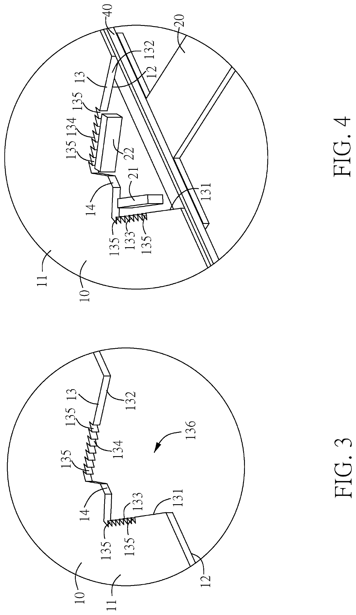
The present disclosure solves the problem of using a few light emitting components to achieve sufficient luminance and illuminance uniformity by using a light guiding plate with an accommodating groove and two light divergence segments. This allows light beams emitted from two light emitting components to be injected into the light guiding plate via the two segments, resulting in a uniform distribution of light beams throughout the plate. These improvements provide sufficient luminance and illuminance uniformity to the keyboard.

Problems solved by technology

However, with the design concept of lightweight, thin, compact and small, the accessible volume of the electronic product for interior functional modules is relatively narrowed down.

Method used


Image

  • Illuminating keyboard and light emitting module thereof
  • Illuminating keyboard and light emitting module thereof
  • Illuminating keyboard and light emitting module thereof

Examples


Embodiment Construction

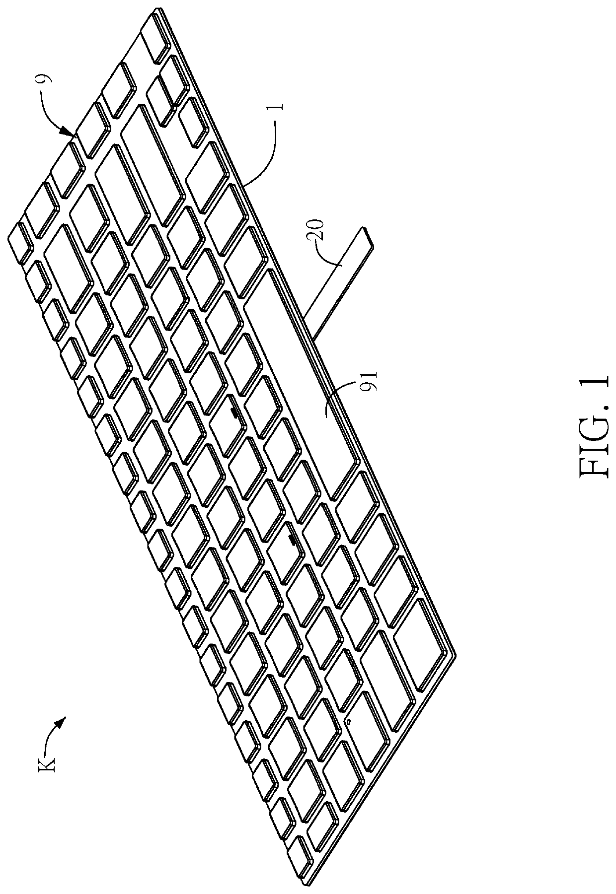
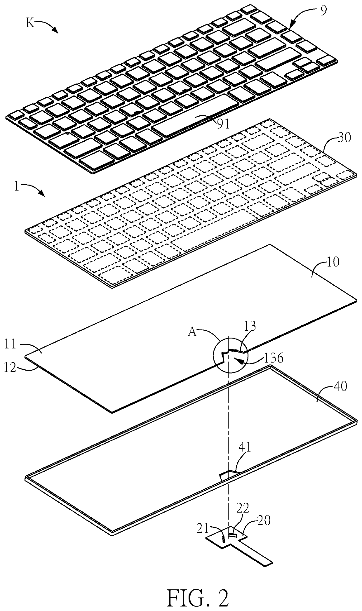
[0029]Please refer to both FIG. 1 and FIG. 2. FIG. 1 illustrates a schematic drawing of an illuminating keyboard K according to one embodiment of the present disclosure; and FIG. 2 illustrates an exploded schematic view of the illuminating keyboard K as shown in FIG. 1. In this embodiment, the illuminating keyboard K comprises a light emitting module 1 and a keyboard module 9. The light emitting module 1 is correspondingly disposed to the keyboard module 9. In this embodiment, the light emitting module 1 is disposed to the bottom of the keyboard module 9. The light emitting module 1 comprises a light guiding plate 10, a circuit board 20, a first light emitting component 21, a second light emitting component 22, a light shielding plate 30 and a reflection plate 40. The light guiding plate 10 includes a first surface 11, a second surface 12 and an accommodating groove 13. According to the view angle of FIG. 2, the first surface 11 is the top surface of the light guiding plate 10, the ...


PUM


Abstract

The present disclosure discloses an illuminating keyboard including a keyboard module and a light emitting module. The keyboard module has an opaque region. The light emitting module includes a light guiding plate, a first light emitting component and a second light emitting component. The light guiding plate includes an accommodating groove corresponding to the opaque region. The accommodating groove has a first sidewall, a second sidewall, a first light divergence segment and a second light divergence segment. The first light divergence segment and the second light divergence segment are disposed on the first sidewall and the second sidewall, respectively. The first light emitting component and the second light emitting component are located in the accommodating groove and are disposed toward the first sidewall and the second sidewall, respectively. The light beams are injected into the light guiding plate via the first and the second light divergence segment.

Description

BACKGROUND OF THE DISCLOSURE1. Field of the Disclosure[0001]The present disclosure relates to an illuminating keyboard; more particularly, relates to a light emitting module of an illuminating keyboard.2. Description of the Related Art[0002]In order to provide a light source with sufficient luminance for an illuminating keyboard, it is necessary to install a sufficient amount of light emitting components. Conventionally, multiple light emitting diodes (i.e., light emitting components) are disposed on a flexible circuit board, and the light emitting diodes along with the flexible circuit board are arranged in columns and placed on the middle of a light guiding plate which is the interlayer of an illuminating keyboard, such that the light emitted by the light emitting diodes can be uniformly spread to the periphery of the illuminating keyboard. However, it still requires at least 6 to 10 light emitting diodes to provide enough luminance and illuminance uniformity.[0003]Furthermore, ac...

Claims


Application Information

Patent Timeline
IPC IPC(8): H01H13/83G06F3/02
CPCH01H13/83G06F3/0202H01H2219/018H01H2219/036H01H2219/056H01H2219/062H01H2219/044H01H2219/064
Inventor HO, HSUAN-WEIHUANG, JIAN-HUA
Owner CHICONY POWER TECH CO LTD
Learn More