Device for ascertaining operating data for a radar sensor

a radar sensor and operating data technology, applied in the direction of measuring devices, using reradiation, instruments, etc., can solve the problems of increasing memory requirements, inability to use mechanisms, and longer time for programming ramp signals, so as to save programming time

Active Publication Date: 2020-03-24
ROBERT BOSCH GMBH
View PDF39 Cites 0 Cited by
  • Summary
  • Abstract
  • Description
  • Claims
  • Application Information

AI Technical Summary

Benefits of technology

[0011]In this way, programming time may advantageously be saved since the ascertainment of ramp data may largely be carried out with the aid of the RF component. An ascertainment of the ramp data external to the RF component is not necessary, whereby a data transmission complexity between the RF component and an external microcontroller may advantageously be reduced. Advantageously, the method according to the present invention may be implemented in a simple manner, e.g., with the aid of firmware.
[0013]One advantageous refinement of the method provides for the defined data of the first subsequence of the ramp signals to include the following: the start frequency of the ramp signal, and the stop frequency of the ramp signal. In this way, a simple option for ascertaining the data of the further subsequences of the ramp signals is advantageously provided.
[0014]One further advantageous refinement of the method provides for the data of the remaining subsequences of the ramp signals to be ascertained by incrementing the start frequency and the stop frequency by a frequency increment. This supports a simple ascertainment of the data of the further subsequences of the ramp signals.
[0016]A further advantageous refinement of the method provides for all data of the subsequences to be stored in the first memory with the aid of a sequence control device of the RF component, in each case prior to the start of a cyclic passage of the method, the data of the next subsequence of the ramp signals being written to the content of the first memory, the frequency increment being retrieved from a second memory. In this way, a further variant of the method is provided, which in addition to saving programming time also allows ramp memory to be saved.

Problems solved by technology

The center frequencies of the frequency ramps must thus rise continuously, as a result of which it is not possible to use a mechanism for repeating the frequency ramps, and thus data for every ramp signal must be explicitly stored in the memory.
This means increased memory requirements, and due to the limited data rate of the control interface also a longer time for programming the ramp signals.

Method used


Image

  • Device for ascertaining operating data for a radar sensor
  • Device for ascertaining operating data for a radar sensor

Examples


Embodiment Construction

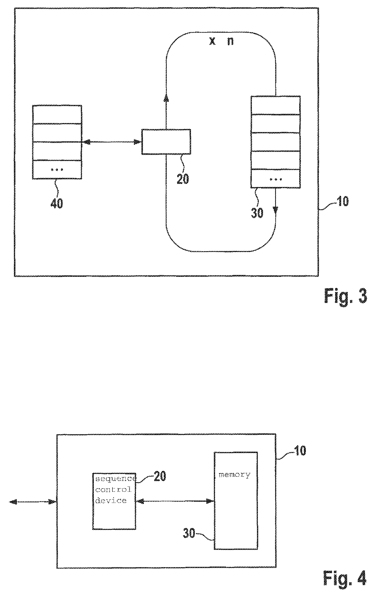
[0023]In accordance with the present invention, a formation of a linear frequency ramp signal from ramp to ramp is carried out according to defined rules, and may thus be calculated by an RF component itself, e.g., in the form of a monolithic microwave integrated circuit (MMIC). In this way, it is advantageously not necessary to ascertain all data for the frequency ramp signals with the aid of an externally situated microcontroller and to transmit these via a data bus to the RF component. As a result, a reduction in computing time is advantageously achievable. Advantageously, the method is independently able to write to ramp memories in the RF component according to a predefined pattern via a software or hardware mechanism.

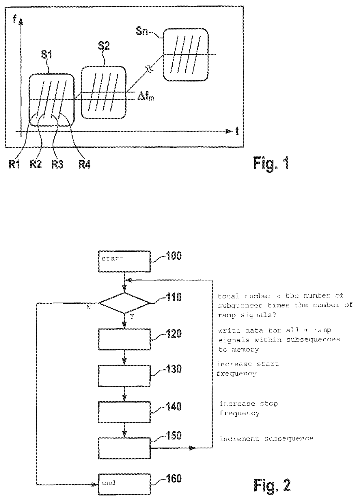
[0024]FIG. 1 basically shows the modulation mechanism for frequency ramps of the radar sensor, which is known per se and implemented with the aid of the provided method. A first subsequence S1 having m=4 ramp signals R1 . . . R4 is apparent, in this case the numbe...


PUM


Abstract

A method for ascertaining operating data of a radar sensor, including transmitting defined data of a first subsequence of ramp signals to an RF component of the radar sensor; ascertaining the data of the remaining subsequences of the ramp signals from the defined values of the first subsequence with the aid of the RF component; and storing the ascertained data of the remaining subsequences in a first memory of the RF component.

Description

CROSS REFERENCE[0001]The present application claims the benefit under 35 U.S.C. § 119 of German Patent Application No. DE 102016202936.3 filed on Feb. 25, 2016, which is expressly incorporated herein by reference in its entirety.FIELD[0002]The present invention relates to a method for ascertaining operating data for a radar sensor. The present invention furthermore relates to a radar sensor.BACKGROUND INFORMATION[0003]Frequency modulated continuous wave (FMCW) radar and chirp sequence modulation are two exemplary types of modulation which are used particularly frequently in automotive radar systems. The chirp sequence modulation is used primarily in corresponding radar sensors, which in contrast to the FMCW method allows the sensor parameters distance and speed to be ascertained separately from one another. For this purpose, a sequence of multiple identical, linear frequency ramps is emitted. In order to reduce memory requirements when explicitly programming each frequency ramp, a r...

Claims


Application Information

Patent Timeline
Patent Type & Authority Patents(United States)
IPC IPC(8): G01S7/35G01S13/93G01S13/34G01S13/931
CPCG01S7/352G01S13/931G01S13/34G01S7/40G01S13/343G01S13/347
Inventor STEINBUCH, DIRKMOERTLBAUER, KARINSTEINHAUER, MATTHIASOTT, MICHAEL
Owner ROBERT BOSCH GMBH
Why Eureka
Try Eureka