Waterproof chip antenna

a chip antenna and antenna body technology, applied in the direction of antennas, radiating element housings, electrical appliances, etc., can solve the problems of short service life, poor waterproofness and low practicability, inconvenient movement of antennas, etc., to improve the overall stability of deconcentrators, prevent water, and improve the airtightness of upper shells and lower shells

Active Publication Date: 2020-03-24
SHENZHEN ANTOP TECH +1
View PDF2 Cites 0 Cited by
  • Summary
  • Abstract
  • Description
  • Claims
  • Application Information

AI Technical Summary

Benefits of technology

[0005]The chip body is generally hung with hard objects penetrating the hanging hole in prior art, such screws and hard rods. According to the present invention, the waterproof chip antenna has a desire advantage that the hanging hole are stressed uniformly through the gasket embedded on the peripheries of the hanging hole so that the hanging hole may avoid wear and tear caused by local stress from the hard objects, which can avoid that the chip body is wear through by the hard objects to make water entry into and thus affecting the signal reception of the antenna. The chip setting mode also facilitates arrangement of the antenna at different places to receive signals better, and the hanging hole facilitate outdoor hanging, making the antenna with high flexibility. In conclusion, the waterproof chip antenna according to the present invention has good waterproofness and is suitable for outdoor use.
[0034]Compared with the prior art, the waterproof chip antenna according to the present invention has beneficial effects. On one hand, the hanging holes are stressed uniformly through the gaskets embedded on the peripheries of the hanging holes, so that the hanging holes may avoid wear and tear caused by local stress from the hard objects, which can avoid that the chip body is wear through by the hard objects to make water entry into and thus affecting the signal reception of the antenna. On the other hand, the chip setting mode facilitates arrangement of the antenna at different places to receive signals better, and the hanging holes also facilitate outdoor hanging, making the antenna with high flexibility. In addition, the sealing ring is arranged between the signal processor and the chip body, so that water is prevented from entering the signal processor to cause short circuit and affect signal reception. The line is divided into the power supply line and the signal line by the deconcentrator, it's convenient connection for users, as the form of the power supply line can be USB plug or common household AC power plug, and the signal line can be common signal line, such as coaxial line. While the existing power supply line and the signal line are combined together through special plugs which may not be matched with electric appliance, so that it's inconvenient connection with the electric appliance for users. According to the present invention, the line is not divided at the signal processor, but divided through a deconcentrator. Such arrangement can prevent water from entering the signal processor and ensure the waterproofness.

Problems solved by technology

An ordinary outdoor antenna is large in size and has a relatively complex overall structure, so that it is different to be maintained due to damage as the antenna is exposed to wind, sun and rain every day, thus resulting high cost and short service life.
In addition, the outdoor antenna can be only rotated within a small range due to fixed installation while the received signal is weak, and the antenna is inconvenient to move, and uneasy to place.
Some planar antennas are in chip structure, however, most of them are indoor antennas with poor waterproofness and low practicability and not suitable for outdoor use because of lack of fully considering all kinds of factors.

Method used


Image

  • Waterproof chip antenna
  • Waterproof chip antenna
  • Waterproof chip antenna

Examples


Embodiment Construction

[0045]The invention will be explained in more detail below in combination with embodiments and attached figures.

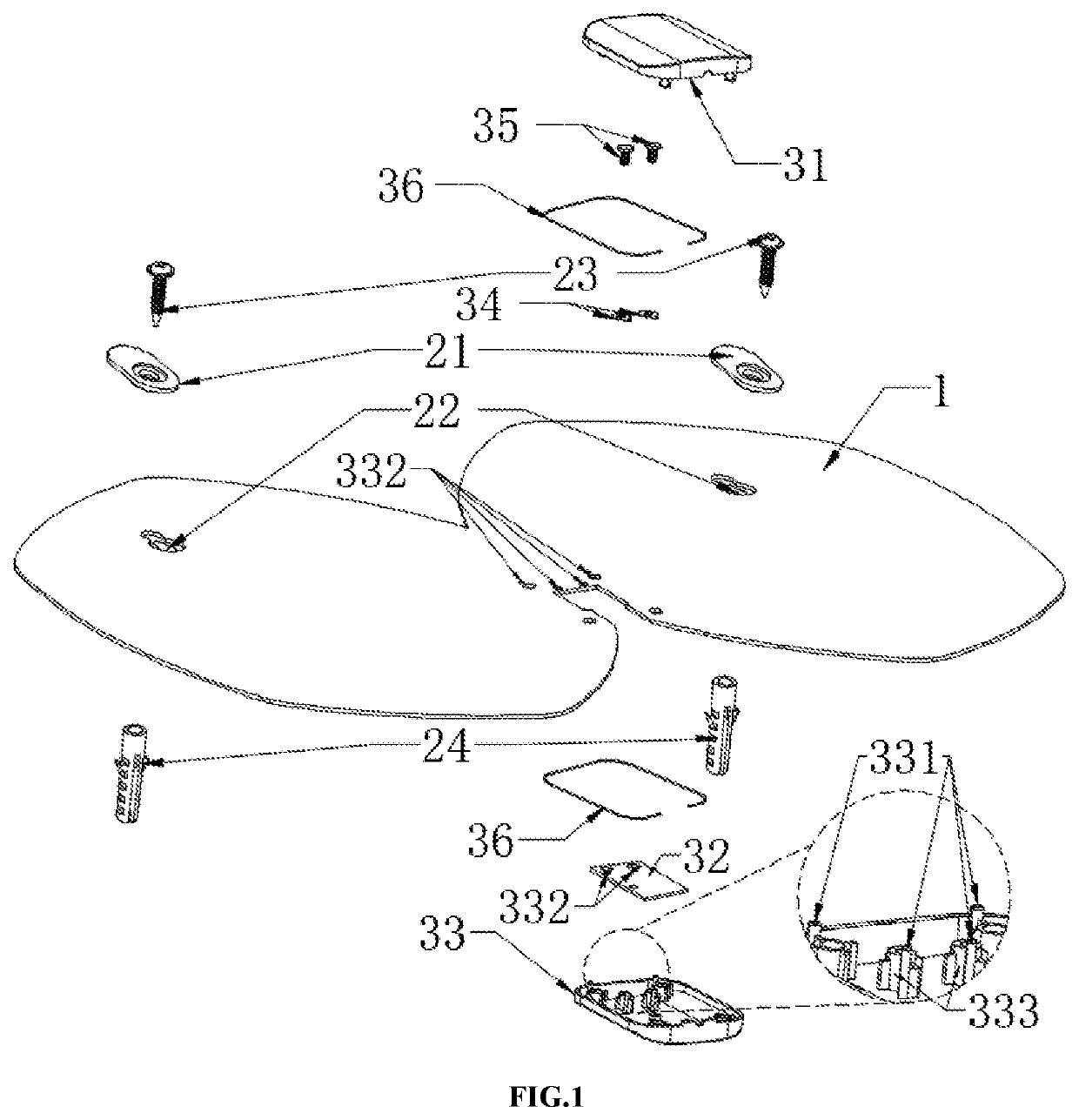
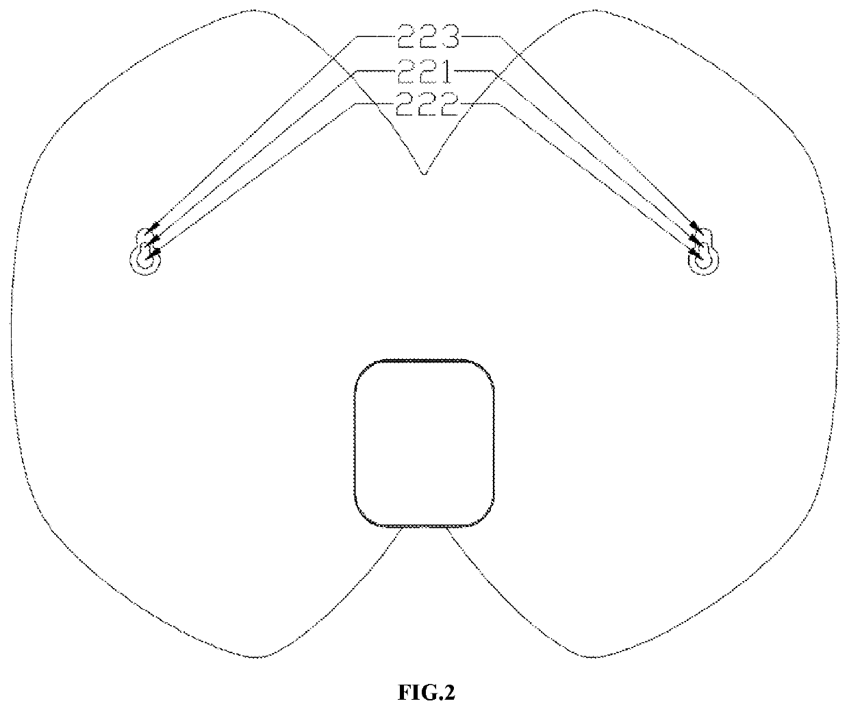
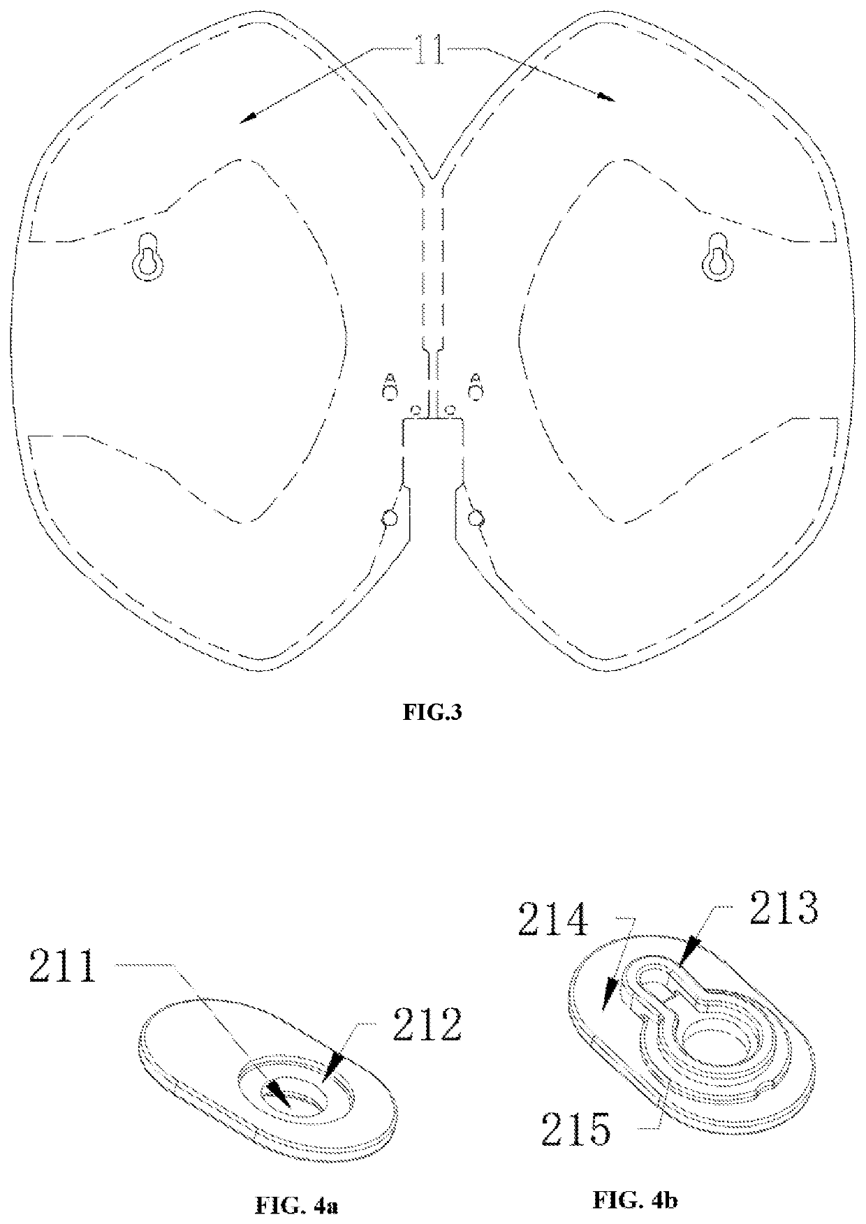
[0046]A waterproof chip antenna as shown in FIG. 1-3 comprises a chip body 1, a signal processor and a deconcentrator 4, wherein the chip body comprises hanging holes 22, gaskets 21 embedded around the hanging holes 22, and an oscillator piece 11 arranged in the chip body 1 (refer to the closed structure as shown by dotted line in FIG. 3); the signal processor is installed on the chip body 1, and the connection position between the signal processor and the chip body is provided with a sealing ring 36; and the oscillator piece 11 is connected to the signal processor. The signal processor is connected to the deconcentrator 4 through a circuitry, comprising a power supply line A and a signal line B which are connected to the circuitry separately, as shown in FIG. 6.

[0047]The chip body 1 is generally hung with hard objects penetrating the hanging holes 22, such as screws and h...


PUM


Abstract

The invention specifically relates to a waterproof chip antenna comprising a chip body including hanging holes, gaskets embedded on the peripheries of the hanging holes, and an oscillator piece arranged in the chip body. The chip body is generally hung with hard objects, such screws and hard rods. Compared with the prior art, the waterproof chip antenna has the advantage that the hanging holes are stressed uniformly through the gasket embedded on the peripheries of the hanging holes to prevent the hanging holes from wear and tear caused by local stress from the hard objects, avoiding that the chip body is wear through by the hard objects to make water entry into and thus affecting the signal reception of the antenna. In addition, the chip setting mode facilitates arrangement of the antenna at different places to receive signals better, and the hanging holes also facilitate outdoor hanging with high flexibility. In conclusion, the waterproof chip antenna according to the present invention has good waterproofness and is suitable for outdoor use.

Description

TECHNICAL FIELD[0001]The invention relates to the field of waterproof antennas, in particular to a waterproof chip antenna.BACKGROUND[0002]Communication media in people's lives are increasing with economic development, while television is an indispensable information medium in the family all the time. With the improvement of living standard, people's requirements for television channels become increasingly higher so that an antenna plays its important role. An ordinary outdoor antenna is large in size and has a relatively complex overall structure, so that it is different to be maintained due to damage as the antenna is exposed to wind, sun and rain every day, thus resulting high cost and short service life. In addition, the outdoor antenna can be only rotated within a small range due to fixed installation while the received signal is weak, and the antenna is inconvenient to move, and uneasy to place. At present, planar antennas on market hold plastic shell generally with thick stru...

Claims


Application Information

Patent Timeline
Patent Type & Authority Patents(United States)
IPC IPC(8): H01Q1/42H01Q1/38H01Q1/12H01Q23/00
CPCH01Q23/00H01Q1/12H01Q1/38H01Q1/42
Inventor YANG, RUIDIAN
Owner SHENZHEN ANTOP TECH
Why Eureka
Try Eureka