
Magnetic connection structure of a spectacle frame for solid connection

a technology of solid connection and magnetic connection, which is applied in the field of eyewear, can solve the problems of inability to separate optical frame and temples, insecure connection, and lack of protective structure of magnets, so as to facilitate assembly and disassembly, increase the flexure strength of the magnet core, and facilitate the front. disassembly.

Active Publication Date: 2020-03-31
TSE CHUN IP
View PDF9 Cites 0 Cited by
  • Summary
  • Abstract
  • Description
  • Claims
  • Application Information

AI Technical Summary

Benefits of technology

The present patent describes a utility model for a magnetic connector that has advanced features such as improved connection, protective effects on the magnet core, and smooth unfolding. The model is aesthetically pleasing and easy to assemble and disassemble. The front edges of the hinges are streamlined and avoid damage to the frame or lens. The overall structural design is simple and firm, providing a high degree of reliability.

Problems solved by technology

However, in a screw structure, the thread would easily strip and render the connection insecure.
After screws are used for connection, they cannot be removed, and the optical frame and temples cannot be separated.
However, in existing magnetic connection structures, there is no protective structure for the magnets.
Because of their fragile texture, the magnets could be easily broken or damaged.
When the fronts or temples are relatively heavy, the magnetic connection alone cannot ensure firm connection between the fronts and temples, which may easily get loose.
As a result, the connection is not firm, the structure is sturdy and has low reliability.
Besides, when the existing temples are unfolded to a linear state, they cannot be further bent, which causes discomfort for wearing.

Method used


Image

  • Magnetic connection structure of a spectacle frame for solid connection
  • Magnetic connection structure of a spectacle frame for solid connection
  • Magnetic connection structure of a spectacle frame for solid connection

Examples


Embodiment Construction

[0049]In light of the drawings and embodiments, this utility model is further described as follows:

[0050]As shown in FIGS. 1-2, a magnetic connection structure of an eyewear for solid connection comprises a front connecting portion 100 and a temple connecting portion 200.

[0051]As shown in FIG. 3, the front connecting portion 100 comprises a front connecting piece 120, the inner side of which is provided with a rectangular stainless iron upper hinge 110; the upper portion of the outer side of the front connecting portion 100 is provided with an one step lower snap fit 121.

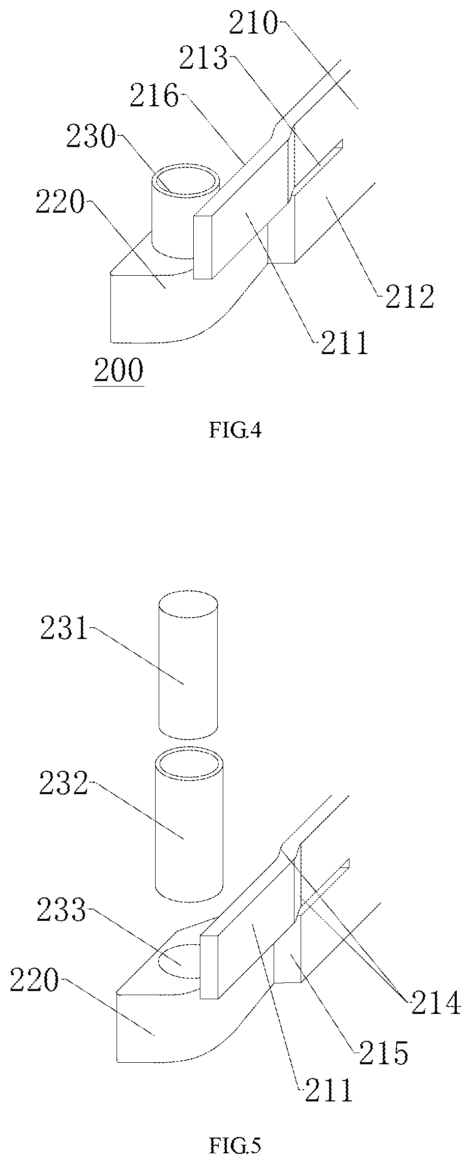
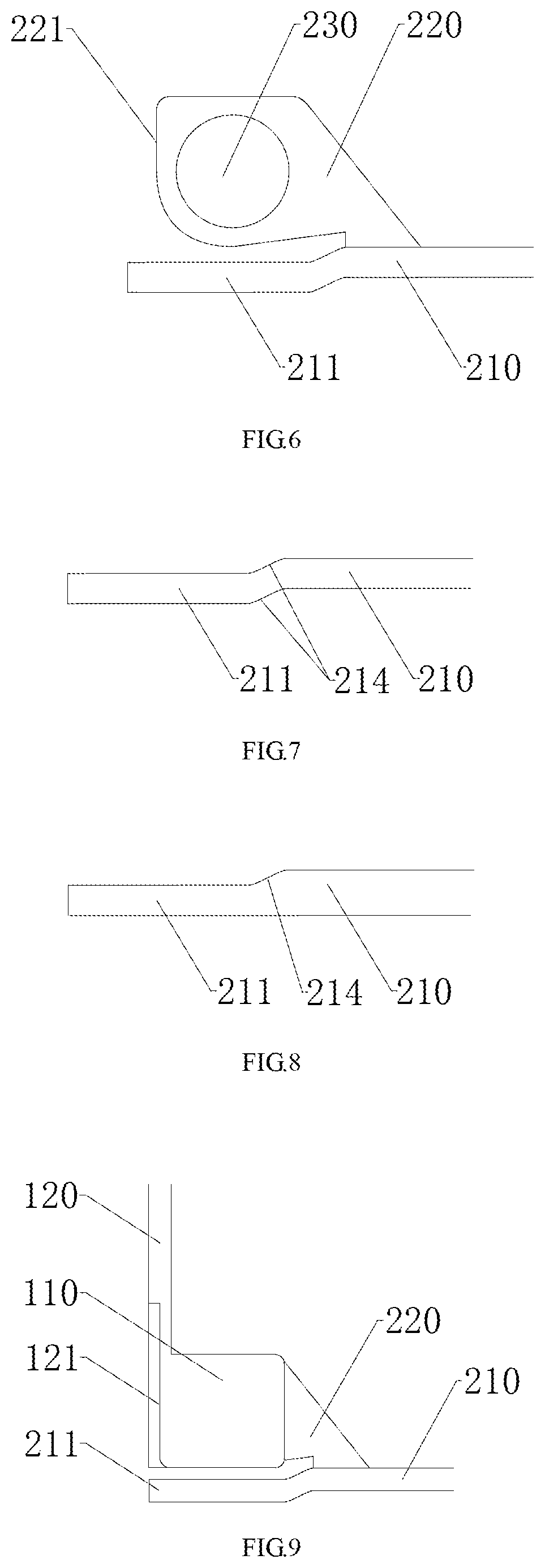
[0052]As shown in FIGS. 4-6, the temple connecting portion 200 comprises a temple connecting piece 210, a magnetic connecting piece 230 and a lower hinge 220; the magnetic connecting piece 230 is fastened to the lower hinge 220, and the upper portion of the magnetic connecting piece 230 matches the upper hinge 110.

[0053]The magnetic connecting piece 230 includes a metal protective shell 232 and a magnet core 231 dis...


PUM


Abstract

This utility model discloses a magnetic connection structure of an eyewear for solid connection, comprising a front connecting portion and a temple connecting portion. The inner side of the front connecting portion is provided with an upper hinge having an upper hinge groove with a downward opening; the upper portion of the outer side of the front connecting portion is provided with an one step lower snap fit. The temple connecting portion comprises a temple connecting piece, a magnetic connecting piece and a lower hinge, wherein said magnetic connecting piece is fastened to the lower hinge, the front end of said temple connecting piece is provided with an elastic piece and a fixing piece, said elastic piece matches the snap fit, and the fixing piece is connected to the lower hinge. This utility model adds protection of the magnet core, the temples and the front would not detach, the temples are elastic and easy to assemble and disassemble. The entire structure is simple, firmly connected, not easy to break and thus highly reliable.

Description

TECHNICAL FIELD[0001]This utility model relates to the field of eyewear, and specifically relates to a magnetic connection structure of an eyewear for solid connection.BACKGROUND ART[0002]For traditional glasses, the front and the temples are fastened by screws. However, in a screw structure, the thread would easily strip and render the connection insecure. After screws are used for connection, they cannot be removed, and the optical frame and temples cannot be separated. Therefore, if one part of the eyewear needs to be replaced, it has to be replaced together with the optical front and the temples.[0003]One solution is to use fronts and temples connected with magnets. However, in existing magnetic connection structures, there is no protective structure for the magnets. Because of their fragile texture, the magnets could be easily broken or damaged. When the fronts or temples are relatively heavy, the magnetic connection alone cannot ensure firm connection between the fronts and te...

Claims


Application Information

Patent Timeline
Patent Type & Authority Patents(United States)
IPC IPC(8): G02C5/22G02C5/16G02C9/02G02C5/02
CPCG02C5/2209G02C5/02G02C5/2254G02C9/02G02C5/16G02C2200/02
Inventor TSE, CHUN IP
Owner TSE CHUN IP
Learn More