Process for manufacturing contact lenses

a manufacturing process and contact lens technology, applied in the field of contact lens manufacturing, can solve the problem of not being able to predict reliably as a rule, and achieve the effect of low lens tearing percentag

Active Publication Date: 2020-04-07
ALCON INC
View PDF11 Cites 0 Cited by
  • Summary
  • Abstract
  • Description
  • Claims
  • Application Information

AI Technical Summary

Benefits of technology

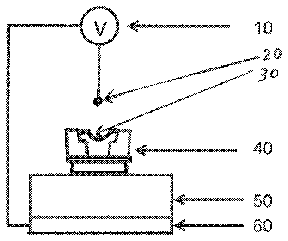
[0006]The invention relates to a method for producing contact lenses, comprising the steps of: (1) obtaining a mold for cast-molding contact lenses from a lens formulation, wherein the mold comprises a first mold half having a first molding surface and a first back surface, a second mold half having a second molding surface and a second back surface, wherein when the first and second mold halves are configured to receive each other such that a lens forming cavity is formed between the first molding surface and the second molding surface; (2) applying a corona discharge on one of the first and second back surfaces so that the molding surface of the mold with the treated back surface has an average water contact angle smaller than the molding surface of the mold with untreated mold by about 0.1 degrees to about 6 degrees; (3) introducing a lens formulation into the lens-forming cavity formed between the first and second molding surfaces; (4) curing the lens formulation in the cavity to form a contact lens; and (5) opening the mold and removing the molded contact lens, wherein the method is characterized by retaining the contact lens on the mold having corona discharge treated back surface and producing low percentages of lens tearing.

Problems solved by technology

Unfortunately, it is not possible as a rule to predict reliably to which of the two mold halves the contact lens will adhere: in some cases it adheres to the male mold half (mold half with the convex molding surface) and, in others, it stays in the female mold half (mold half with the concave molding surface).

Method used


Image

  • Process for manufacturing contact lenses

Examples


Embodiment Construction

[0009]The present invention may be understood more readily by reference to the following detailed description of the invention taken in connection with the accompanying drawing FIGURES, which form a part of this disclosure. It is to be understood that this invention is not limited to the specific devices, methods, conditions or parameters described and / or shown herein, and that the terminology used herein is for the purpose of describing particular embodiments by way of example only and is not intended to be limiting of the claimed invention. Any and all patents and other publications identified in this specification are incorporated by reference as though fully set forth herein.

[0010]Also, as used in the specification including the appended claims, the singular forms “a,”“an,” and “the” include the plural, and reference to a particular numerical value includes at least that particular value, unless the context clearly dictates otherwise. Ranges may be expressed herein as from “abou...


PUM

PropertyMeasurementUnit
water contact angleaaaaaaaaaa

Abstract

The invention provides a method of making ophthalmic lenses with an enhanced quality and enhanced yield achieved by using molds having been treated on back surface of mold with corona discharge technique. The method comprises the steps of obtaining a mold for cast-molding contact lenses from a lens formulation, wherein the mold comprises a first mold half having a first molding surface and a first back surface, a second mold half having a second molding surface and a second back surface, wherein when the first and second mold are configured to receive each other such that a lens forming cavity is formed between the first molding surface and the second molding surface and applying a corona discharge on one of the first and second back surfaces so that the molding surface of the mold with the treated back surface has an average water contact angle smaller than the molding surface of the mold with untreated mold by about 0.1 degrees to about 6 degrees.

Description

[0001]This application claims the benefit under 35 U.S.C. § 119 (e) of U.S. provisional Application No. 62 / 270,938 filed Dec. 22, 2015, the content of which are incorporated by reference in its entirety.[0002]The present invention relates generally to a process for producing contact lenses, in particular, silicone hydrogel contact lenses, using molds having been treated on back surface of mold with corona discharge technique.BACKGROUND OF THE INVENTION[0003]In the manufacture of contact lenses by the so-called full-mold process (casting process), contact lenses are usually produced by dispensing a specific amount of a polymerizable contact lens material into the female mold half. The mold is then closed by putting on the male mold half, a molding cavity being enclosed between the two molding surfaces. In that molding cavity there is the previously dispensed contact lens material, which is polymerized to form an as yet unhydrated contact lens. Subsequently, the mold is opened and the...

Claims


Application Information

Patent Timeline
Patent Type & Authority Patents(United States)
IPC IPC(8): B29D11/00B29C59/10G02C7/04B29K105/00B29L11/00
CPCB29D11/00192G02C7/049B29D11/0048B29C59/10B29D11/00134B29L2011/0041B29K2105/0061
Inventor JOBE, OLIHAKEN, UWE
Owner ALCON INC
Why Eureka
Try Eureka