Drain valve

a technology of drain valve and handle, which is applied in the field of drain valves, can solve the problems of user's inability to push the button or rotate the handle, and reduce the comfort level, and achieve the effects of convenient and fast use, short lift stroke, and improved comfort level for users

Active Publication Date: 2020-04-07
ECO XIAMEN TECH INC
View PDF1 Cites 0 Cited by
  • Summary
  • Abstract
  • Description
  • Claims
  • Application Information

AI Technical Summary

Benefits of technology

[0016]Through this configuration, on the one hand, when the drain valve is in the closed static state, the second valve element bears a downward resultant force of the upward buoyancy force of the floating body, the downward water pressure in the inner cavity, the gravity of the lifting component and the gravity of its own to close the water outlet, and the first valve element closes the drain outlet under the effect of the pressure in the inner cavity and the gravity of its own; when the second valve element is lifted to the first opening position, water in the inner cavity is rapidly discharged, and water in an external water tank passes through the drain window and the water supply channel to enter the inner cavity; and as the draining speed is much higher than the inflow speed, the pressure in the inner cavity is rapidly decreased, the downward force borne by the second valve element is drastically decreased accordingly, the buoyancy force of the floating body is greater than the gravity of the lifting component and the second valve element in water, and thus, the second valve element bears a large upward resultant force to automatically float upwards to a limit height. On the other hand, after the second valve element is opened, water in the inner cavity is rapidly discharged via the drain outlet, the water pressure, applied to the upper surface of the first valve element, in the inner cavity is rapidly decreased, the original balanced water pressure state of the inner cavity and the outer cavity is broken, and under the effect of an upward resultant force of the upward water pressure from the outer cavity and the buoyancy force, the first valve element overcomes the gravity of its own to automatically float upwards to open the drain outlet of the valve body and to reach the maximum opening height H. In this way, the lift stroke h for the first valve element to reach the set opening height H to open the drain outlet is much smaller than that of traditional drain valves (as for the lift stroke of the traditional drain valves, H=h), and thus, the drain valve can be used by users more conveniently.
[0026]Compared with traditional drain valves, the drain valve of the invention realizes the same draining effect with a short lift stroke, is convenient and fast to use, and improves the comfort level for users.

Problems solved by technology

For instance, as for a 3-inch drain valve with a large valve element, the lift stroke may be very long, which makes it difficult for users to push the button or to rotate the handle, consequentially, decreasing the comfort level.

Method used


Image

  • Drain valve
  • Drain valve
  • Drain valve

Examples


Embodiment Construction

[0032]To make the objective, technical scheme and advantages of the invention clearer, a detailed illustration of the embodiments of the invention is given in combination with the drawings as follows. However, those ordinarily skilled in this field would appreciate that various technical details for readers to better understand the application are presented in the embodiments of the invention, but even without these technical details, the technical scheme claiming for protection by the claims of the application can still be realized based on various variations and modifications of the following embodiments.

[0033]The invention is introduced in combination with the drawings as follows.

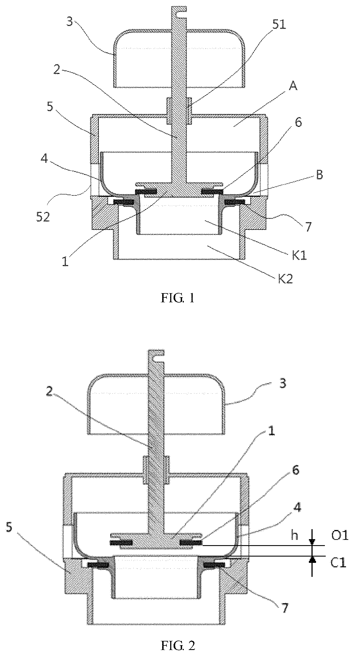
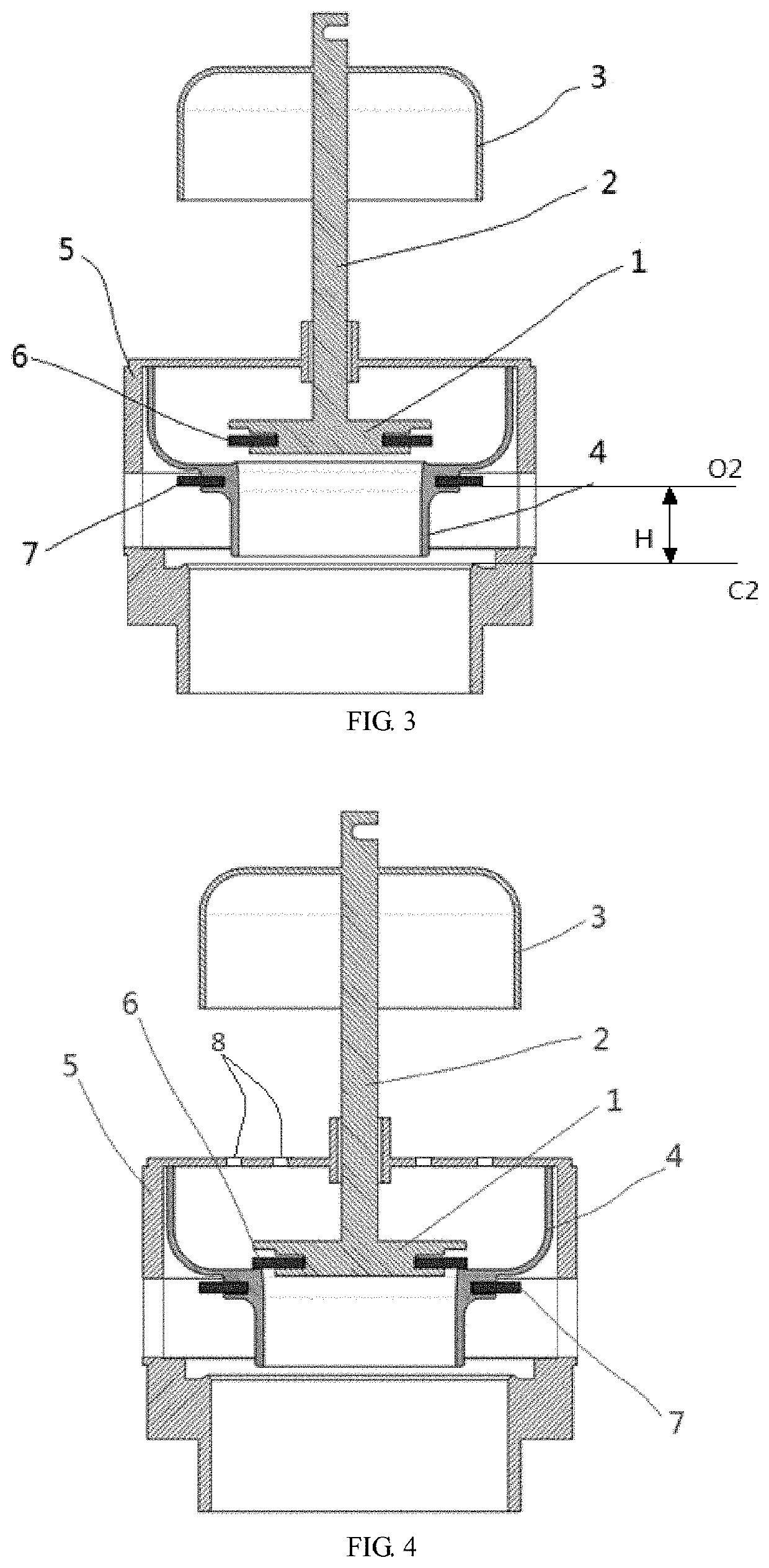
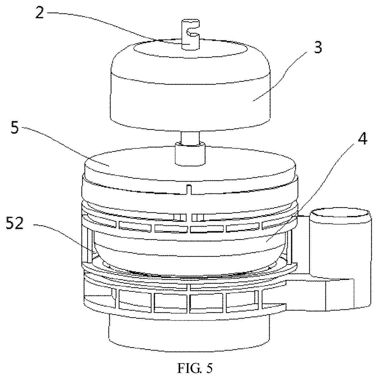
[0034]One preferred embodiment of the invention provides a drain valve. As shown in FIG. 1, the drain valve includes a valve body 5, a first valve element 4, a second valve element 1 and a lifting component 2, wherein a drain outlet K2 is formed in the lower portion of the valve body 5; the first valve e...


PUM


Abstract

A drain valve includes a valve body provided with a drain outlet in the lower portion, a first valve element arranged in the valve body to open or close the drain outlet, dividing the valve body into an inner cavity and an outer cavity and provided with a water outlet communicated with the drain outlet, a second valve element located in the inner cavity to open or close the water outlet of the first valve element, and a lifting component having an end connected with the second valve element and provided with a floating body assisting the lifting component in lifting the second valve element with a buoyancy force. Compared with traditional drain valves, the drain valve realizes the same draining effect with a short lift stroke, is convenient and fast to use, and improves the comfort level for users.

Description

BACKGROUND OF THE INVENTIONTechnical Field[0001]The invention relates to the field of bathroom accessories, in particular to a drain valve.Description of Related Art[0002]In modern society, flush toilets have been widely applied to the daily life of people. Drain valves are disposed in water tanks of toilets to be used for draining and flushing. When traditional drain valves typically of a lever-type structure are used, the lever mechanism is made to work to lift a pull rod by pushing a button or by rotating a handle, and then, the valve element is opened to discharge water. The lift stroke of the drain valves of this structure is large and is generally about 20 mm. For instance, as for a 3-inch drain valve with a large valve element, the lift stroke may be very long, which makes it difficult for users to push the button or to rotate the handle, consequentially, decreasing the comfort level.BRIEF SUMMARY OF THE INVENTION[0003]In order to solve the above-mentioned problems and to ove...

Claims


Application Information

Patent Timeline
Patent Type & Authority Patents(United States)
IPC IPC(8): E03D1/35
CPCE03D1/35
Inventor PENG, JINXINGCHEN, YOUFEN
Owner ECO XIAMEN TECH INC
Why Eureka
Try Eureka