Thermally actuated dryer door lock

a dryer and door lock technology, applied in the field of clothes dryers, can solve the problems of fire in the dryer, and achieve the effect of increasing the damage to the building

Active Publication Date: 2020-04-07
ILLINOIS TOOL WORKS INC
View PDF34 Cites 0 Cited by
  • Summary
  • Abstract
  • Description
  • Claims
  • Application Information

AI Technical Summary

Benefits of technology

[0005]The present invention provides a thermally actuated door lock which will hold the dryer door closed in the event of a dryer fire, counteracting any tendency of the user to open the door, which may promote the fire (by providing a source of air to the fire through the open door) and which may expose the user to possible personal injury and / or increase damage to the building from smoke and flame passing out of the open door. Additionally, the thermally actuated door lock may help prevent the door from being blown open in the case of explosive combustion that may occur when smoldering materials ignite a gas build up within the dryer drum. In one embodiment, the thermally actuated door lock is activated at combustion temperatures by a melting of a fusible material holding a spring-loaded bolt in retraction when the fusible material melts; a released spring-loaded bolt may then engage the door to prevent it from opening.
[0009]It is thus a feature of at least one embodiment of the invention to provide sufficient lateral resistance against an opening of the appliance door when there is a fire and to help resist melting of the bolt at fire temperatures.
[0013]It is thus a feature of at least one embodiment of the invention to provide simplified installation of the thermally actuated lock into a pre-existing mounting hole and to provide a structure that will maintain the housing against the hole without allowing it to slide through.
[0015]It is thus a feature of at least one embodiment of the invention to provide stability in the mounting of the housing against the appliance in a way that permits rapid installation of the thermally actuated lock.
[0019]It is thus a feature of at least one embodiment of the invention to reduce the amount of fusible material both allowing it to melt faster and reducing the cost of the lock.
[0021]It is thus a feature of at least one embodiment of the invention to provide a simple and reliable means to bias the bolt toward the extended position.

Problems solved by technology

Clothing dried in this manner will often release fabric threads and the like which form combustible lint which may be trapped in a lint screen to be periodically cleaned by the user.
The presence of heated air and the combustible material of the lint, the latter of which may accumulate throughout the dryer particularly if the lint filter is not cleaned or replaced, and / or the cleaning of clothes containing combustible fluids can on rare occasions cause a dryer fire in which materials within the dryer begin to burn.

Method used


Image

  • Thermally actuated dryer door lock
  • Thermally actuated dryer door lock
  • Thermally actuated dryer door lock

Examples


Embodiment Construction

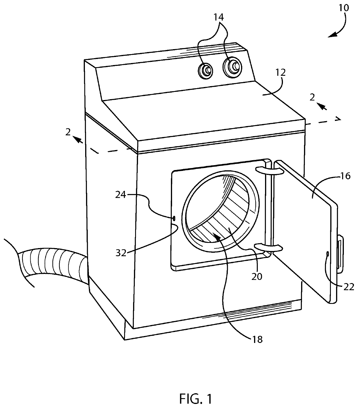
[0030]Referring now to FIG. 1, a dryer 10 may provide a housing 12, typically constructed of sheet-metal, such as enameled sheet steel or the like. The housing 12 may provide a generally box-like outer surface presenting at its upper rear edge dryer controls 14. The dryer controls 14 may communicate with a motor for driving an internal rotating tumbler drum 20 and an air blower (not shown), and with a heater system (not shown) all generally understood in the art. In this way the dryer controls 14 may fully control operation of the dryer 10, for example, according to a drying time set by the consumer.

[0031]A front face of the housing 12 may support a door 16 hinging along the vertical axis at one vertical edge of the housing 12 to cover or reveal an opening 18 through which a tumbler drum 20 may be accessed for insertion of wet clothing into the tumbler drum 20. After insertion of clothing into the tumbler drum 20, the door 16 may be closed over tumbler drum 20 to retain the clothes ...


PUM


Abstract

A thermally actuated lock for an appliance incorporates a fusible material that holds a spring-loaded bolt in retraction. Temperatures that would indicate an appliance fire allow the bolt to extend between the housing and appliance door to lock the appliance door in a closed position.

Description

CROSS REFERENCE TO RELATED APPLICATION[0001]This application is a national phase of International Application Number PCT / US2013 / 025125 filed Feb. 7, 2013, which claims the benefit of U.S. provisional application 61 / 597,296 filed Feb. 10, 2012 and hereby incorporated in its entirety by reference.FIELD OF THE INVENTION[0002]The present invention relates to clothes dryers and the like and specifically to a lock assembly for preventing opening of the dryer door in the event of a dryer fire.BACKGROUND OF THE INVENTION[0003]Clothes dryers typically provide a rotating drum perforated with openings to allow forced airflow through the drum walls while the clothes are tumbled within the rotating drum. The drum is normally held within an appliance housing to rotate along a horizontal axis to promote tumbling action while the drum opening is covered by a housing door to retain the clothes therein. The forced air through the drum walls may be heated by an electrical or gas heating element to inc...

Claims


Application Information

Patent Timeline
Patent Type & Authority Patents(United States)
IPC IPC(8): E05B65/10A62C2/06D06F39/14D06F58/20A62C2/04D06F37/42
CPCE05B65/104D06F58/20D06F39/14A62C2/04D06F58/30A62C3/14D06F58/50D06F37/42
Inventor KUEHN, KURT A.MORGAN, KARL S.DAVIS, MICHAEL W.HERZOG, RICHARD R.WONG, CHONG B.DAM, ROBERTDRELICHARZ, JOHN G.
Owner ILLINOIS TOOL WORKS INC
Why Eureka
Try Eureka