
Hybrid vehicle

a hybrid vehicle and hybrid technology, applied in the direction of fluid gearing, electric propulsion mounting, gearing, etc., can solve the problems of corresponding and achieve the effect of reducing the upsizing of hybrid vehicles and corresponding cooling of rotating machines

Active Publication Date: 2020-04-14
TOYOTA JIDOSHA KK
View PDF31 Cites 0 Cited by
  • Summary
  • Abstract
  • Description
  • Claims
  • Application Information

AI Technical Summary

Benefits of technology

[0005]The present disclosure provides a hybrid vehicle that can achieve downsizing and cool a rotating machine.
[0010]Hereby, in the hybrid vehicle of the present disclosure, a distance between the rotating machine and the differential ring gear can be made closer in a radial direction of the differential ring gear, so that an oil scooped up by the differential ring gear can be easily poured over the rotating machine, thereby making it possible to improve coolability of the rotating machine.
[0012]Hereby, in the hybrid vehicle of the present disclosure, the oil scooped up by the differential ring gear is easily poured over the rotating machine, thereby making it possible to improve coolability of the rotating machine.
[0014]As such, in the hybrid vehicle of the present disclosure, the clutch is placed on the inside-diameter side of the rotor included in the rotating machine, thereby making it possible to shorten a length of the transaxle in the axial direction in comparison with a case where the rotating machine and the clutch are serially placed side by side in the axial direction of the output shaft of the engine.
[0017]In the hybrid vehicle of the present disclosure, the rotating machine is accommodated in the same case as the damper, the torque converter, and the transmission mechanism, and a space where an oil accumulated in the case and the rotating machine can make contact with each other is formed in the case. Hereby, the oil and the rotating machine can make contact with each other in the space, so that the rotating machine can be cooled. Thus, it is not necessary to provide an exclusive cooling device for cooling the rotating machine, thereby making it possible to restrain upsizing of the hybrid vehicle correspondingly. This yields such an effect that downsizing is achieved and the rotating machine can be cooled.

Problems solved by technology

The hybrid vehicle described in JP 10-339185 A separately requires an exclusive cooling device configured to cool the rotating machine that generates heat by operating, which causes a problem to cause upsizing of the hybrid vehicle correspondingly.

Method used


Image

  • Hybrid vehicle
  • Hybrid vehicle
  • Hybrid vehicle

Examples


Embodiment Construction

[0029]The following describes one embodiment of an FF (front-engine front-wheel drive) hybrid vehicle to which the present disclosure is applied, with reference to the drawings. Note that the present disclosure is not limited by the present embodiment, but can be also applied to a hybrid vehicle that employs a rear-engine rear-wheel drive (RR) system, for example.

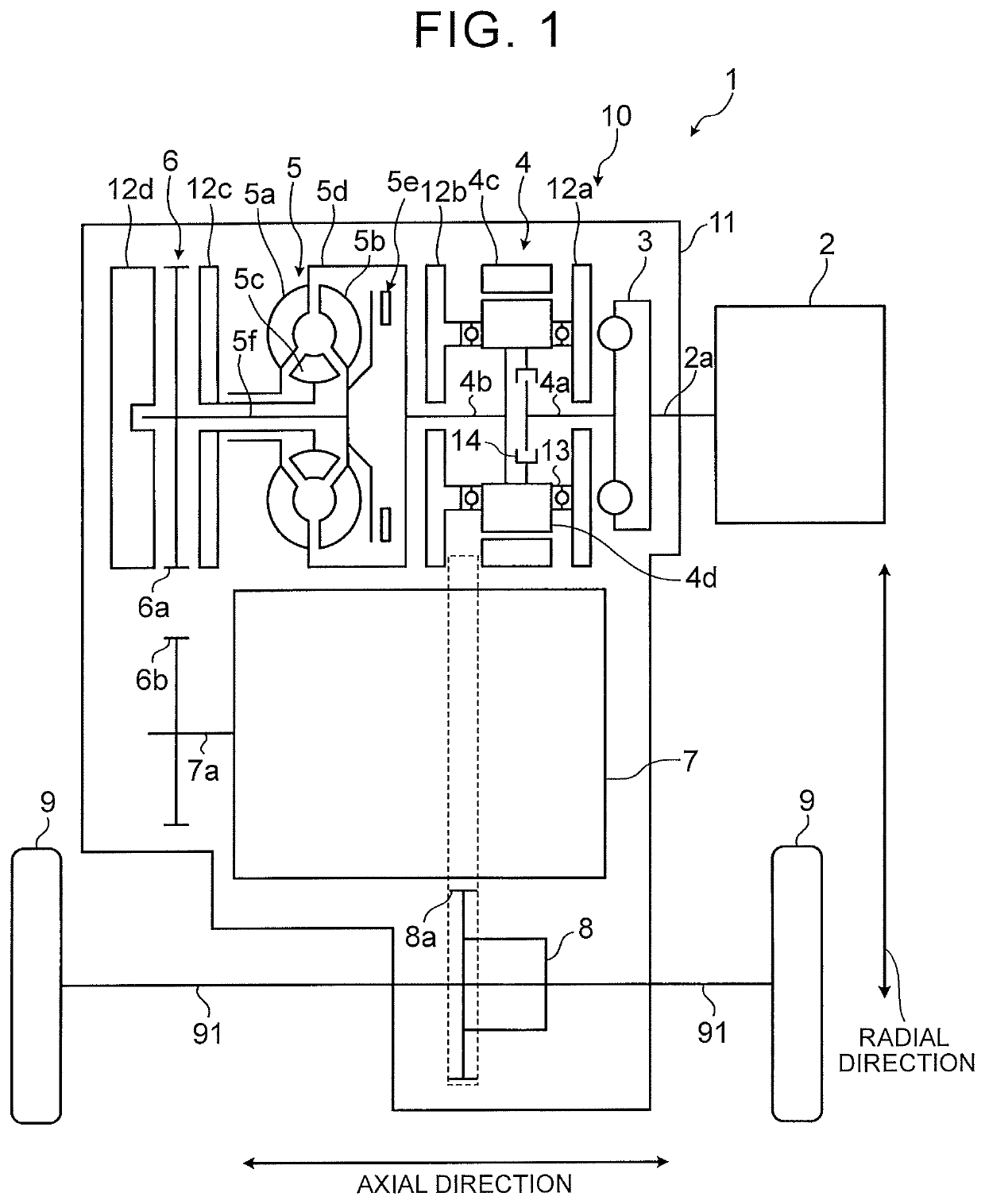
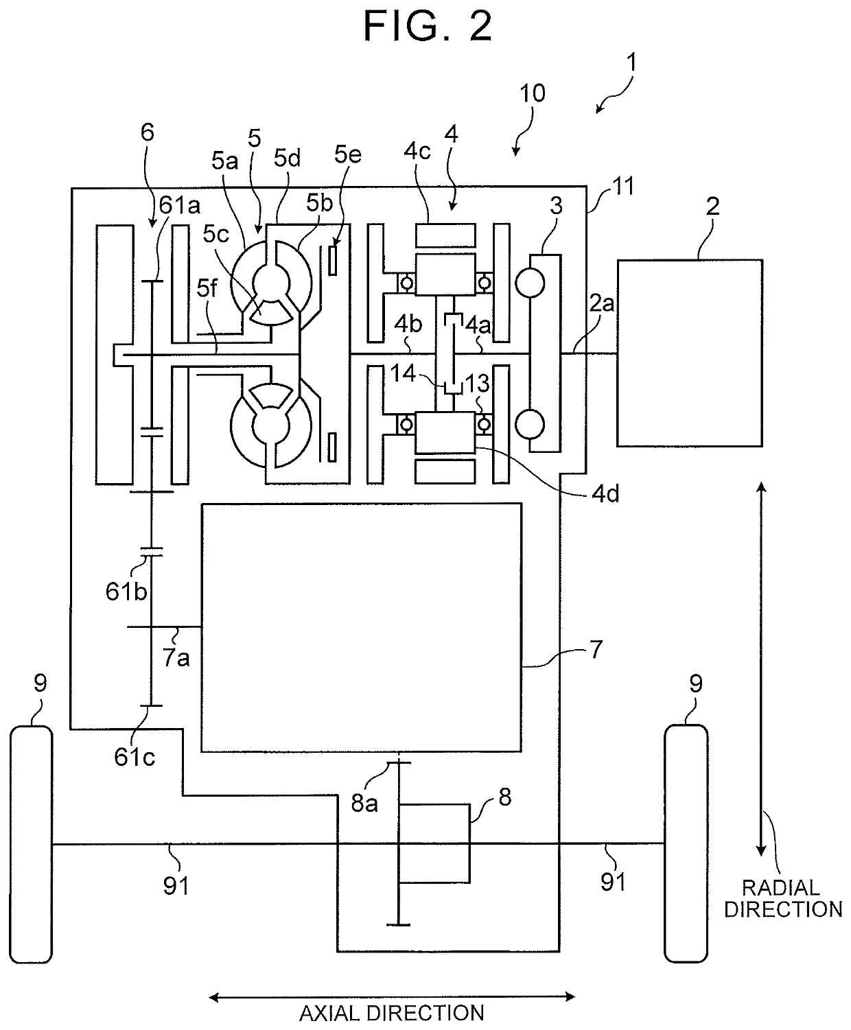
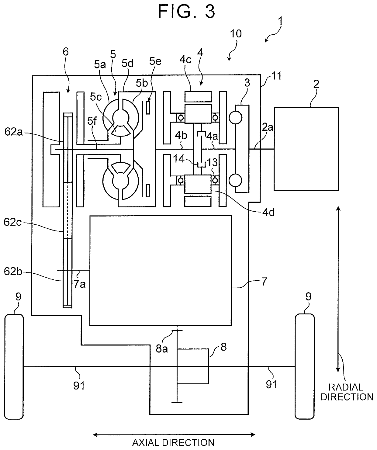
[0030]FIG. 1 is a skeleton diagram of a hybrid vehicle 1 according to the embodiment. As illustrated in FIG. 1, the hybrid vehicle 1 of the embodiment includes an engine 2, a transaxle 10, and a pair of driving wheels 9.

[0031]The transaxle 10 is configured such that a damper 3, a motor generator 4 as a rotating machine, a torque converter 5, a power transmission mechanism 6, a transmission mechanism 7, a differential 8, and the like are accommodated in a transaxle case 11, which is a housing of the transaxle 10. The transaxle 10 constitutes a power transmission device that transmits a driving torque input from the engine 2 ...


PUM


Abstract

A hybrid vehicle includes: an engine including an output shaft configured to output a power; a damper placed on a first axis that is the same axis as the output shaft; a rotating machine placed on the first axis; a torque converter placed on the first axis; a transmission mechanism placed so that an input shaft of the transmission mechanism is positioned on a second axis that is an axis different from the first axis; a case in which the rotating machine and the transmission mechanism are accommodated; driving wheels attached to drive shafts; and an oil accumulated in a lower part of a space surrounded by the case and used for lubrication of the transmission mechanism, the oil being in contact with a part of the rotating machine.

Description

INCORPORATION BY REFERENCE[0001]The disclosure of Japanese Patent Application No. 2017-005835 filed on Jan. 17, 2017 including the specification, drawings and abstract is incorporated herein by reference in its entirety.BACKGROUND1. Technical Field[0002]The present disclosure relates to a hybrid vehicle.2. Description of Related Art[0003]Japanese Patent Application Publication No. 10-339185 (JP 10-339185 A) discloses a front-engine front-wheel drive (FF) hybrid vehicle including an engine, a rotating machine, a transaxle, drive shafts, driving wheels, and the like. A damper, a torque converter, a transmission mechanism, a differential, and the like are provided in a case of the transaxle, and the damper and the torque converter are placed on the same axis as an output shaft of the engine. Further, the transmission mechanism is placed such that the output shaft of the engine and an input shaft of the transmission mechanism are placed on the same axis, but the output shaft of the engi...

Claims


Application Information

Patent Timeline
Patent Type & Authority Patents(United States)
IPC IPC(8): B60K6/48B60K6/26B60K6/365B60K6/38B60K6/405F16H57/04B60K11/02B60K1/00F16H45/02B60K6/543B60L50/16
CPCB60K6/26F16H57/0476B60K6/405B60K11/02B60K6/48B60K6/365B60K6/38F16H57/0484Y10S903/904F16H45/02B60K2006/264B60K2006/4825B60K6/543B60Y2200/92B60Y2304/01B60K2001/006F16H57/0489F16H2045/0221F16H57/0483B60K2006/262F16H57/0457B60K6/50B60K17/16B60K23/02B60L50/16Y02T10/62Y02T10/70
Inventor SEKIGUCHI, TADASHIITOU, YOSHIOYANAGIDA, TOMOAKIOSADA, TOMOEASAOKA, HIRONORI
Owner TOYOTA JIDOSHA KK
Learn More