Core structure of housingless-type oil cooler

Inactive Publication Date: 2007-06-07
CALSONIC KANSEI CORP
View PDF8 Cites 1 Cited by
  • Summary
  • Abstract
  • Description
  • Claims
  • Application Information

AI Technical Summary

Benefits of technology

[0013] Therefore, the air, having a low heat-transfer coefficient, in the heat-transfer chambers suppresses heat transfer between

Problems solved by technology

The above known conventional core structures of the housingless-type oil coolers, however, encounter a problem in that coolability of the oil cooler deteriorates because the low-temperature oil, which is cooled by the cooling wa

Method used


Image

  • Core structure of housingless-type oil cooler
  • Core structure of housingless-type oil cooler
  • Core structure of housingless-type oil cooler

Examples


Example

[0044] The inner fin 13 is an offset fin in the first embodiment, but may be used another type one. The inner fin 13 is formed with first to fifth through-holes 13a to 13e corresponding to the first to fifth cylindrical portions 11a to 11e of the first plate 11 and to the first to fifth cylindrical portions 12a to 12e of the second plate 12.

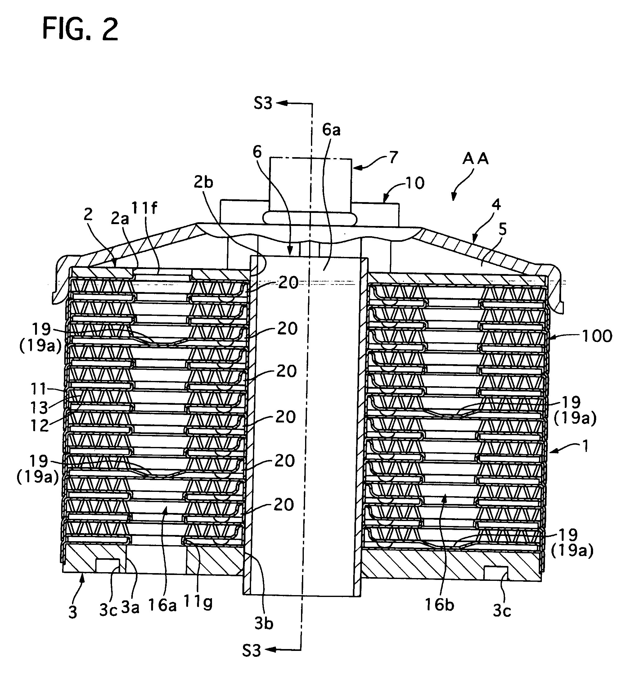
[0045] The first plate 11 and the second plate 12 are coupled with each other, containing the inner fin 13 therein, to form an inner space therebetween for containing the inner fin 13, thereby forming the cooling element. The inner space forms an oil chamber 15 as shown in FIGS. 4B and 5B.

[0046] The second and third cylindrical portions 11b and 11c of the first plate 11 and the second and third cylindrical portions of the next second plate 12 are fitted with each other, as shown in FIG. 4B, to form a pair of oil passages 16a and 16b for fluidically connecting with the adjacent oil chambers 15.

[0047] On the other hand, the second plate 12 and i...

Example

[0062] Next, a core structure of a housingless-type oil cooler of a second embodiment according to the present invention will be described with reference to the accompanying drawings.

[0063] As shown in FIG. 9A, in the core structure of the housingless-type oil cooler BB of the second embodiment, a first plate 11 has a first cylindrical portion 11a projecting downward and shaped in a large circular cylinder at it center position. The first cylindrical portion 11a has a bending portion 21, at an upper end portion thereof, narrowing its opening as a position of the first cylindrical portion 11a becomes lower.

[0064] On the other hand, a second plate 12 has a first cylindrical portion 12a projecting downward, not having a bending portion like the first embodiment.

[0065] The first plate 11 and the second plate 12 are coupled with each other, containing an inner fin 13 therebetween, to form a cooling element. A plurality of the cooling elements are piled up in a vertical direction to fo...


PUM


Abstract

A housingless-type oil cooler includes cooling elements having first and second plates coupled with together, an oil return tube vertically arranged through a core portion, and a heat-transfer suppressing means. The cooling elements are piled up in a vertical direction of the core portion to alternately form cooling water chambers and oil chambers so that the adjacent cooling water chambers are fluidically connected through a cooling water passage and the adjacent oil chambers are fluidically connected through an oil passage. The oil return tube discharges oil introduced from one side of the core portion toward its other side through the oil chambers and the oil passages. The heat-transfer suppressing means is arranged between the oil chambers and the oil return tube to suppress heat transfer between the oil flowing in the oil chambers and the oil flowing in the oil return tube.

Description

BACKGROUND OF THE INVENTION [0001] 1. Field of the Invention [0002] The present invention relates to a core structure of a housingless-type oil cooler which has a plurality of plates piled up to form cooling water chambers and oil chambers therebetween without an additional housing so as to cool oil flowing through the oil chambers. [0003] 2. Description of the Related Art [0004] Conventional oil coolers are used for and attached to, for example, automatic transmissions to cool oil thereof. Some of the conventional ones are constructed to have an oil tube forming an oil chamber and arranged in a cooling water chamber formed between a housing of the oil cooler and the oil tube. The other conventional ones are, what is called, a housingless-type oil cooler, which is constructed to have a plurality of plates to alternately form cooling water chambers and oil chambers therebetween for removing a housing, thereby decreasing its manufacturing costs and dimensions. [0005] Specifically, suc...

Claims


Application Information

Patent Timeline
IPC IPC(8): F28F3/08
CPCF28D9/0012F28D9/005F28F13/00
Inventor MATSUDAIRA, NORIMITSU
Owner CALSONIC KANSEI CORP
Why Eureka
Try Eureka