Plated member and plated terminal for connector

a technology of plated terminals and connectors, which is applied in the manufacture of contact members, superimposed coating processes, transportation and packaging, etc., can solve the problems of insufficient heat resistance of conventional tin plated terminals, large insertion force, and large damage to the terminal surface during insertion, so as to achieve small variation, small space distribution, and high in-plane uniformity

Active Publication Date: 2017-09-05
AUTONETWORKS TECH LTD +2
View PDF20 Cites 4 Cited by
  • Summary
  • Abstract
  • Description
  • Claims
  • Application Information

AI Technical Summary

Benefits of technology

[0029]Since the silver-tin alloy layer is hard, the hard plated member is obtained in an initial state and softening is unlikely to occur after being left in the heating environment. As just described, the plated member according to the present invention simultaneously has a low friction coefficient and heat resistance in the sense of both suppressing an increase of the contact resistance value and suppressing softening.
[0041]According to the method for producing a plated terminal for connector according to the present invention, the silver-tin alloy layer and the silver coating layer on the outermost surface can be simultaneously formed only by a simple and inexpensive process.

Problems solved by technology

Further, since the terminal becomes larger in conformity with a current capacity, a larger insertion force is required and damage on a terminal surface during insertion becomes larger.
However, conventional tin plated terminals are insufficient in heat resistance when being used with such a large current.
However, since copper particles easily diffuse in a silver plating layer, there is a problem that copper components reach a silver plating surface and the oxidized copper components increase resistance in the case of applying silver plating to a surface of a terminal base material made of copper of copper alloy.
This causes a problem of increasing a terminal insertion force and increasing a friction coefficient.
In Japanese Unexamined Patent Publication No. 2009-79250, a main plating layer is the soft silver layer and sufficient abrasion resistance cannot be obtained even if the hard silver layer is formed thereon.
Even if the Ni underplating is formed, it is insufficient to prevent the diffusion of copper atoms from the base material.
As just described, in any case, heat resistance is insufficient, i.e. a resistance increase caused by being left at high temperature is not suppressed.
Furthermore, since the hard silver plating is softened by being left in the heating environment in the configuration of Japanese Unexamined Patent Publication No. 2009-79250, heat resistance in the sense of preventing softening caused by being left at high temperature also cannot be obtained.
In addition, since a plating layer is produced by a special film forming method in any of methods of cited literatures 1 to 4, production cost increases.

Method used


Image

  • Plated member and plated terminal for connector
  • Plated member and plated terminal for connector
  • Plated member and plated terminal for connector

Examples


example 1

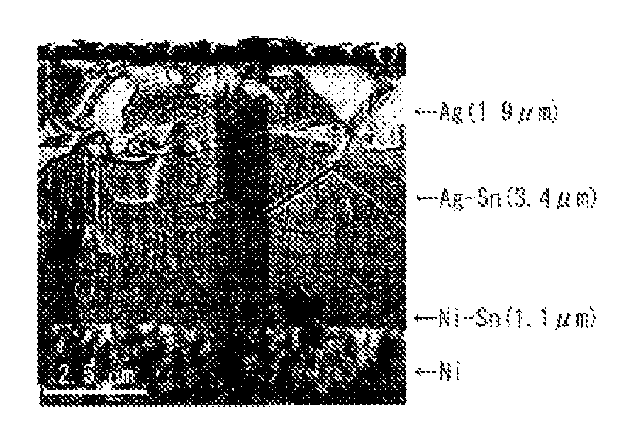
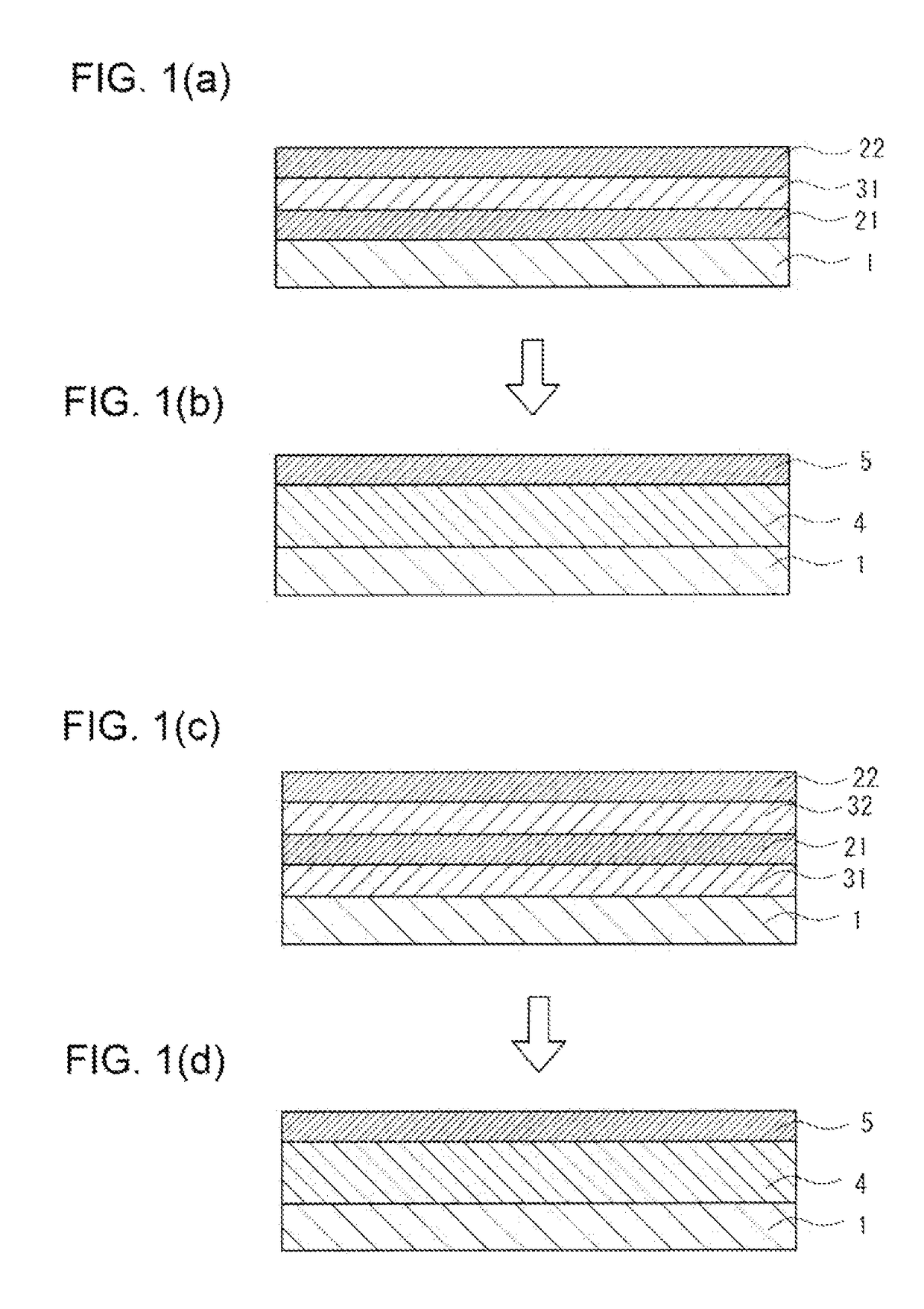
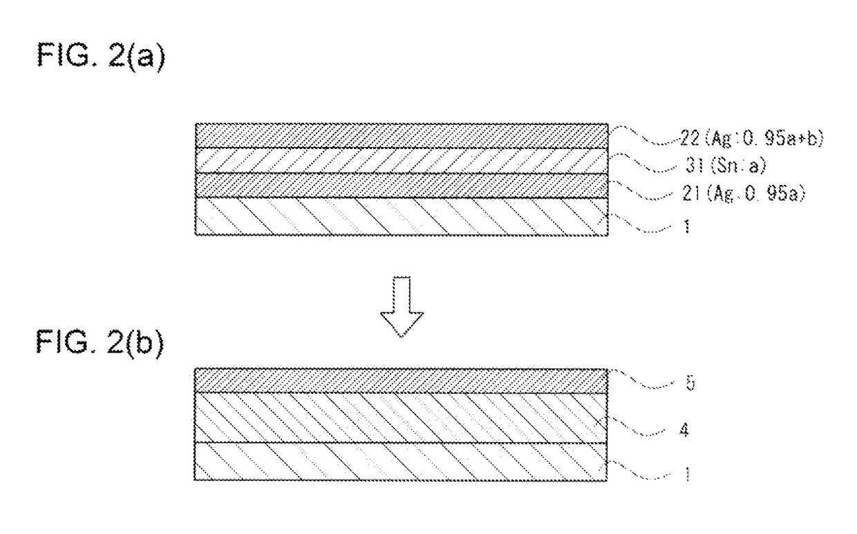
[0090]A nickel under plating layer having a thickness of 0.5 μm was formed on a clean surface of a copper base plate. A soft silver plating layer having a target thickness of 1μ was formed on this nickel under plating layer. A tin plating layer having a target thickness of 1μ was formed on this soft silver plating layer, and a soft silver plating layer having a thickness of 2 μm was formed on the tin plating layer. This material was heated at 200° C. for 60 min in the atmosphere, thereby forming a plated member according to Example 1. Specific formation conditions of the soft silver plating layer and the tin plating layer were as follows.

[0091]

[0092]A plating bath having an Ag concentration of 45 g / L was used

[0093]Operating temperature: 30° C.

[0094]Current density: 5 ASD (2.5 μm / min)

[0095]Plating time: 20 to 30 sec (thickness of plating layer: 1 μm), 40 to 60 sec (thickness of plating layer: 2 μm)

[0096]

[0097]A plating bath having an Sn concentration of 60 g / L was used

[0098]Additive:...

example 2

[0102]As in Example 1, a plated member in which a soft silver plating layer having a target thickness of 1 μm, a tin plating layer having a target thickness of 1 μm and a soft silver plating layer having a target thickness of 2 μm were successively laminated on a surface of a copper base plate to which nickel plating was applied was heated at 290° C. for 1 min.

example 3

[0103]A plated member in which a soft silver plating layer having a thickness of 1.5 μm, a tin plating layer having a thickness of 1.0 μm and a soft silver plating layer having a thickness of 2.5 μm were successively laminated on a surface of a copper base plate to which nickel plating was applied was heated at 290° C. for 1 min.


PUM

PropertyMeasurementUnit
friction coefficientaaaaaaaaaa
thicknessaaaaaaaaaa
thicknessaaaaaaaaaa

Abstract

It is aimed to provide a plated member and a plated terminal for connector, to which a large current can be applied and which have both a low friction coefficient and high heat resistance, at low cost and provide a method for producing such a plated member and a method for producing such a plated terminal for connector. A silver-tin alloy layer for coating a surface of a base material made of copper or copper alloy and a silver coating layer for coating the silver-tin alloy layer and to be exposed on an outermost surface are simultaneously formed by heating to obtain a plated member after tin and silver plating layers are alternately laminated on the surface of the base material with the outermost surface formed by the silver plating layer.

Description

BACKGROUND OF THE INVENTION[0001]1. Field of the Invention[0002]The present invention relates to a plated member, a plated terminal for connector, a method for producing a plated member and a method for producing a plated terminal for connector and more particularly to a plated member and a plated terminal for connector containing silver and tin in a plating layer and methods for producing them.[0003]2. Description of the Related Art[0004]In recent years, high-output motors have been used in hybrid vehicles, electric vehicles and the like. Since a large current flows in a connector terminal such as a terminal for high-output motor to which a large current is applied, the amount of heat generation in a terminal portion increases. Further, since the terminal becomes larger in conformity with a current capacity, a larger insertion force is required and damage on a terminal surface during insertion becomes larger. The terminal is inserted and withdrawn a large number of times for mainte...

Claims


Application Information

Patent Timeline
Patent Type & Authority Patents(United States)
IPC IPC(8): C25D5/10C23C28/02C23C30/00C22C5/06C23C14/58C23C28/00C25D5/12B32B15/01H01R43/16C25D5/50H01R13/03C23C14/16
CPCH01R13/03B32B15/01B32B15/018C22C5/06C23C14/16C23C14/165C23C14/58C23C14/5806C23C28/00C23C28/02C23C28/021C23C28/023C23C30/00C23C30/005C25D5/10C25D5/12C25D5/50H01R43/16Y10T428/1291Y10T428/12708Y10T428/12715Y10T428/12722Y10T428/12896Y10T428/2495Y10T428/24942Y10T428/24967Y10T428/24975Y10T428/26Y10T428/263Y10T428/264Y10T428/265C25D5/611C25D5/617
Inventor SUNAGA, TAKAHIROSAKA, YOSHIFUMISAITOU, YASUSHI
Owner AUTONETWORKS TECH LTD
Why Eureka
Try Eureka