Low temperature coefficient oscillator

Inactive Publication Date: 2010-07-08
ITE TECH INC
View PDF3 Cites 4 Cited by
  • Summary
  • Abstract
  • Description
  • Claims
  • Application Information

AI Technical Summary

Benefits of technology

[0008]The present invention is related to a low temperature coefficient oscillator, which can generate a frequency with a low temperature coefficient, and an area of the low temperature coefficie

Problems solved by technology

Since currents generated by a current mirror circuit in the oscillator circuit have the same temperature coefficient, the voltage and charge current used for generating the output frequency of the oscillator circuit also have the same temperature coefficient, and since the resistor generally has a relatively high temperature coeffi

Method used


Image

  • Low temperature coefficient oscillator
  • Low temperature coefficient oscillator
  • Low temperature coefficient oscillator

Examples


Embodiment Construction

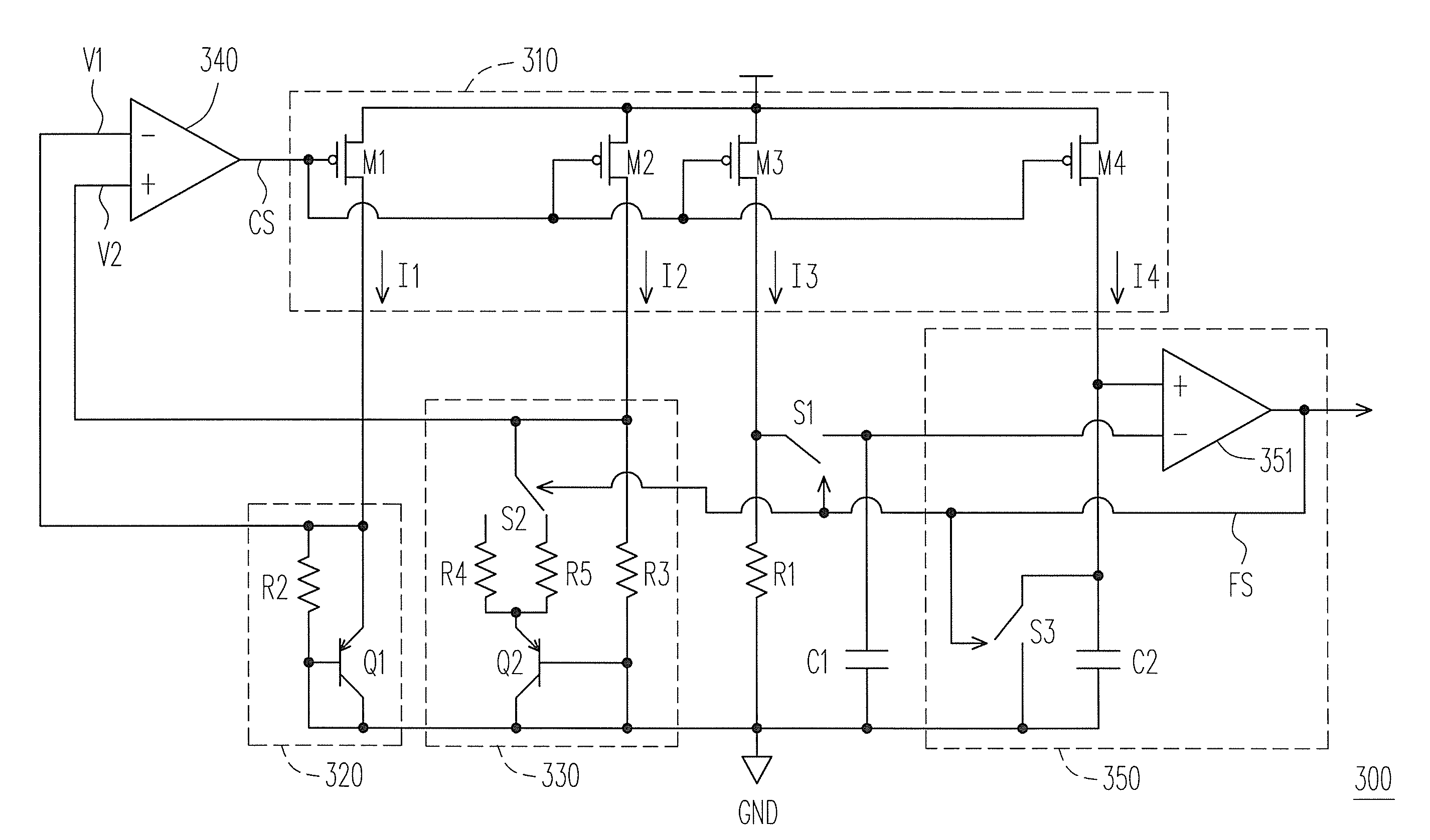
[0023]FIG. 3 is a schematic diagram illustrating a low temperature coefficient oscillator according to an embodiment of the present invention. Referring to FIG. 3, the low temperature coefficient oscillator 300 includes a current generator 310, a first voltage generator 320, a second voltage generator 330, an amplifier 340, a first resistor R1, a first switch S1, a first capacitor C1 and an oscillating unit 350.

[0024]The current generator 310 generates a first current I1, a second current I2, a third current I3 and a fourth current I4 according to a control signal CS. The first voltage generator 320 is coupled to the current generator 310, and generates a first voltage V1 according to the first current I1. The second voltage generator 330 is coupled to the current generator 310, and generates a second voltage V2 according to the second current I2 and a frequency signal FS.

[0025]The amplifier 340 generates the control signal CS according to the first voltage V1 and the second voltage...


PUM


Abstract

A low temperature coefficient oscillator including a current generator, a first and a second voltage generator, an amplifier, a resistor, a switch, a capacitor and an oscillating unit is provided. The current generator generates a first through a fourth current according to a control signal. The first voltage generator generates a first voltage according to the first current. The second voltage generator generates a second voltage according to the second current and a frequency signal. The amplifier generates the control signal according the first and second voltages. The resistor is coupled between a first terminal of the switch and ground, and a first terminal thereof receives the third current. The switch is conducted or not according the frequency signal. The capacitor is coupled between a second terminal of the switch and ground. The oscillating unit generates the frequency signal according to the fourth current and a voltage of the capacitor.

Description

CROSS-REFERENCE TO RELATED APPLICATION[0001]This application claims the priority benefit of Taiwan application serial no. 98100169, filed Jan. 6, 2009. The entirety of the above-mentioned patent application is hereby incorporated by reference herein and made a part of specification.BACKGROUND OF THE INVENTION[0002]1. Field of the Invention[0003]The present invention relates to an oscillator. More particularly, the present invention relates to a low temperature coefficient oscillator.[0004]2. Description of Related Art[0005]FIG. 1 is a schematic diagram illustrating a conventional silicon oscillator. Referring to FIG. 1, the silicon oscillator 100 charges a capacitor through a current I. When the capacitor is charged to a predetermined voltage V, a switch is triggered and is turned on, so that capacitor is discharged to the ground GND. Then, the switch is turned off, and the capacitor is recharged. By such means, the capacitor is repeatedly charged / discharged, so that the silicon osc...

Claims


Application Information

Patent Timeline
IPC IPC(8): G05D23/20
CPCH03B5/24
Inventor CHOU, YI-CHUNGCHEN, TUNG-SHAN
Owner ITE TECH INC
Why Eureka
Try Eureka