
Sintered valve seat

a valve seat and valve body technology, applied in the field of valve seats, can solve the problems of high production cost of metal-sodium-filled valves, power-decreasing knocking, high engine temperature, etc., and achieve the effects of high hardness, high hardness, and high hardness

Active Publication Date: 2020-02-18
RIKEN CO LTD
View PDF32 Cites 0 Cited by
  • Summary
  • Abstract
  • Description
  • Claims
  • Application Information

AI Technical Summary

Benefits of technology

The present invention relates to a valve seat with good wear resistance and deformation resistance. The invention includes a skeleton structure made up of hard particles that prevent deformation of copper or its alloy. The hard particles are replaced with lower-hardness particles to prevent too high hardness. The first hard particles ensure a high filling density, while the second hard particles are in an irregular shape that increases the contact of hard particles and contributes to the formation of a dense skeleton structure. The valve seat also includes a network-shaped copper matrix formed by fine copper powder and excellent wear resistance. The coolability of the valve is improved to reduce abnormal combustion in high-compression-ratio, high-efficiency engines.

Problems solved by technology

Improvement in the efficiency of engines inevitably results in higher engine temperatures, which may cause power-decreasing knocking.
However, the metal-sodium-filled valves suffer such a high production cost that they are not used widely except some vehicles.
The Cu-based alloy valve seats produced by the laser cladding method, which do not contain hard particles, have insufficient wear resistance, suffering seizure by impact wear.
Also, the direct buildup-welding on cylinder heads needs the drastic change of cylinder head production lines and large facility investment.
However, the Cu content of at most about 20% in Patent References 3 and 4 fails to sufficiently improve the thermal conductivity.
Though Patent Reference 5 teaches that Al2O3-dispersion-hardened Cu powder can be produced by heat-treating Cu—Al alloy powder atomized from a Cu—Al alloy melt in an oxidizing atmosphere for selective oxidation of Al, there is actually limit of increasing the purity of an Al2O3-dispersed Cu matrix formed from an Al-dissolved Cu—Al alloy.
The inclusion of more hard particles (for example, 40-50% by weight) increases attackability to a valve, a mating member, and the inclusion of less hard particles (for example, 10-20% by weight) deteriorates the deformation resistance and wear resistance of the valve seat, resulting in remarkably contradictory tendency with respect to the amount of hard particles.

Method used


Image

  • Sintered valve seat

Examples


example 1

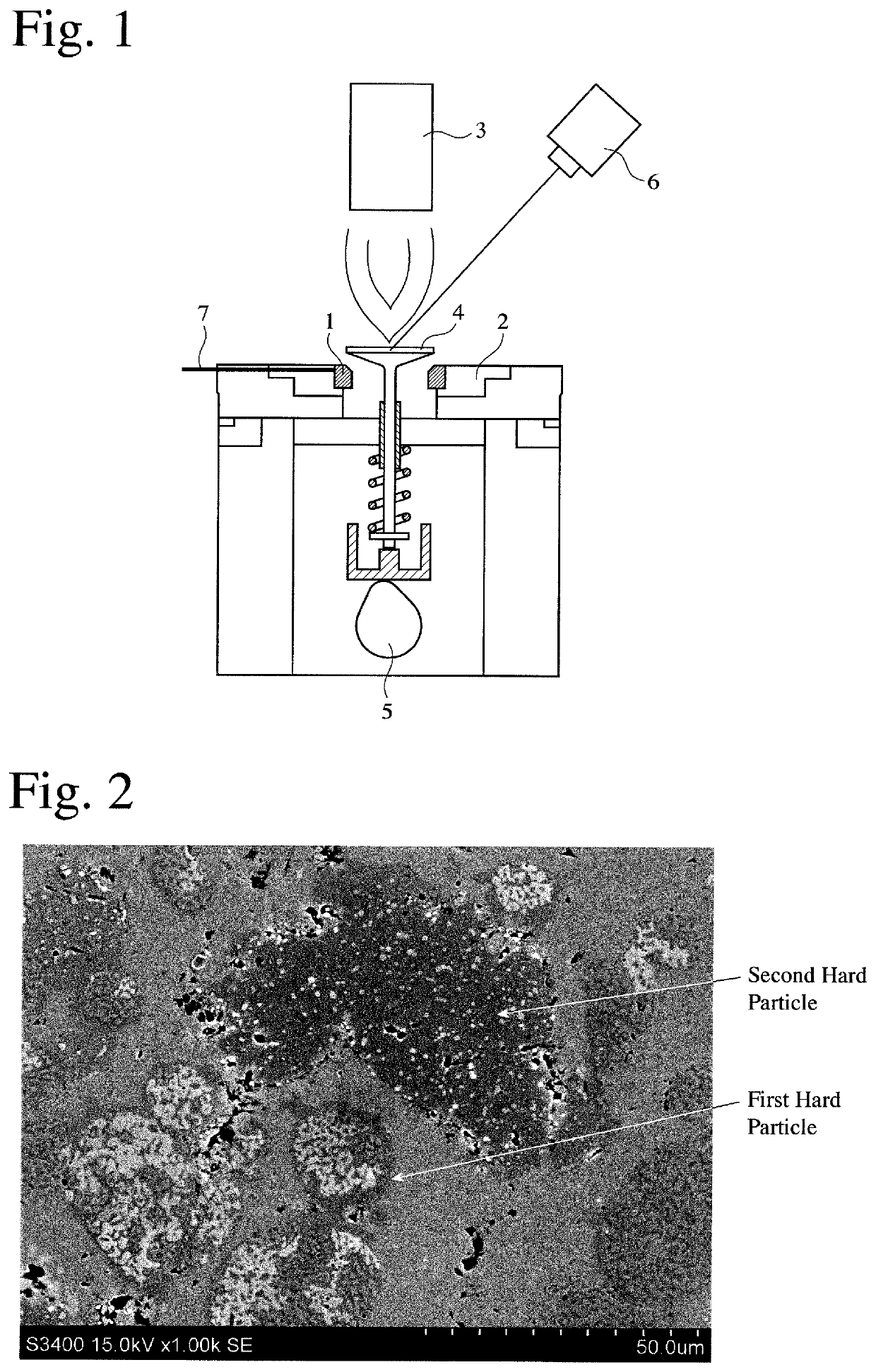
[0040]Electrolytic Cu powder having an average diameter of 22 μm and purity of 99.8% was mixed with 35% by mass of Co—Mo—Cr—Si alloy powder 1A having a median diameter of 72 μm and comprising by mass 28.5% of Mo, 8.5% of Cr, and 2.6% of Si, the balance being Co and inevitable impurities, which was a mixture of spherical particles and irregular-shaped particles, as the first hard particles; 15% by mass of high-speed tool steel powder 2A having a median diameter of 84 μm and comprising by mass 0.85% of C, 0.3% of Si, 0.3% of Mn, 3.9% of Cr, 4.8% of Mo, 6.1% of W, and 1.9% of V, the balance being Fe and inevitable impurities, which were in an irregular shape, as the second hard particles; and 1.0% by mass of Fe—P alloy powder containing 26.7% by mass of P as a sintering aid, to produce a mixture powder in a mixer. Incidentally, 0.5% by mass of zinc stearate for good parting in the molding step was added to each starting material powder.

[0041]The mixture powder was compression-molded at...


PUM

PropertyMeasurementUnit
median diameteraaaaaaaaaa
temperatureaaaaaaaaaa

Abstract

To provide a press-fitting, sintered valve seat having excellent valve coolability enabling use in high-efficiency engines, as well as excellent deformation resistance and wear resistance, first and second hard particles differing in hardness are dispersed in a total amount of 25-70% by mass in a network-shaped Cu matrix, the second hard particles having hardness of 300-650 HV0.1, lower than that of the first hard particles, and 0.08-2.2% by mass of P is contained in the sintered valve seat.

Description

FIELD OF THE INVENTION[0001]The present invention relates to a valve seat for engines, particularly to a press-fitting, high-thermal-conductivity, sintered valve seat capable of suppressing the temperature elevation of a valve.BACKGROUND OF THE INVENTION[0002]To provide automobile engines with improved fuel efficiency and higher performance for environmental protection, so-called downsizing for reducing engine displacement by 20-50% is recently accelerated. Also, direct-injection engines are combined with turbochargers to increase compression ratios. Improvement in the efficiency of engines inevitably results in higher engine temperatures, which may cause power-decreasing knocking. Accordingly, improvement in the coolability of parts particularly around valves has become necessary.[0003]As a means for improving coolability, Patent Reference 1 discloses a method for producing an engine valve comprising sealing metal sodium (Na) in a hollow portion of a hollow valve stem. With respect...

Claims


Application Information

Patent Timeline
Patent Type & Authority Patents(United States)
IPC IPC(8): C22C38/00C22C19/07C22C38/24C22C38/34C22C1/04C22C32/00B22F5/00F01L3/02C22C38/04C22C38/22C22C38/02B22F1/00B22F1/05B22F1/105
CPCB22F1/007B22F1/0011C22C32/0021C22C32/0047C22C38/04C22C38/24B22F5/008C22C19/07C22C1/0425C22C38/00C22C1/04C22C32/0078C22C38/02F01L3/02C22C38/22C22C38/34F01L2810/02B22F2304/10B22F3/1007F01L2820/01B22F2998/10B22F2301/15C22C1/05B22F2999/00B22F2301/10B22F2201/20F01L2103/01B22F2301/35B22F3/02F01L2303/01B22F1/105B22F1/05
Inventor HASHIMOTO, KIMIAKI
Owner RIKEN CO LTD
Learn More