Piezoelectric print head and piezoelectric ink jet printer

a piezoelectric and print head technology, applied in printing and other directions, can solve the problems of increasing the risk of deterioration, and increasing the risk of ink deterioration, so as to reduce the risk of liquid deterioration, and reduce the risk of piezoelectric print head temperature rise

Active Publication Date: 2020-04-21
SEIKO EPSON CORP
View PDF6 Cites 0 Cited by
  • Summary
  • Abstract
  • Description
  • Claims
  • Application Information

AI Technical Summary

Benefits of technology

[0008]An advantage of some aspects of the invention is reducing the risk of deterioration of liquid to be ejected from a piezoelectric print head.

Problems solved by technology

However, as the density of arrangement of the piezoelectric print head increases, the heat amount per unit volume increases.
The increase in heat amount changes the composition of ink and the properties of ink such as viscosity, thereby increasing the risk of deterioration of ink.
The increase in the risk of deterioration represents an increase in possibility that an intended product cannot be obtained due to ejection failure or deterioration of ink.
This may impair the advantage of the piezoelectric print head of ejecting various kinds of liquid such as ink without applying heat to the liquid.
Electric power is consumed and heat is generated with the switch operation.
Hence, the cooling effect due to ejection of liquid and filling with new liquid is not obtained, and consequently the temperature rises.
When liquid to be ejected from a nozzle has properties that are deteriorated at a temperature lower than 100° C., the generation of heat with the switch operation is a serious problem.

Method used


Image

  • Piezoelectric print head and piezoelectric ink jet printer
  • Piezoelectric print head and piezoelectric ink jet printer
  • Piezoelectric print head and piezoelectric ink jet printer

Examples


embodiment

1. Embodiment

[0040]A piezoelectric ink jet printer 1 according to an embodiment is described below with reference to the drawings.

1-1. Overview of Piezoelectric Ink Jet Printer

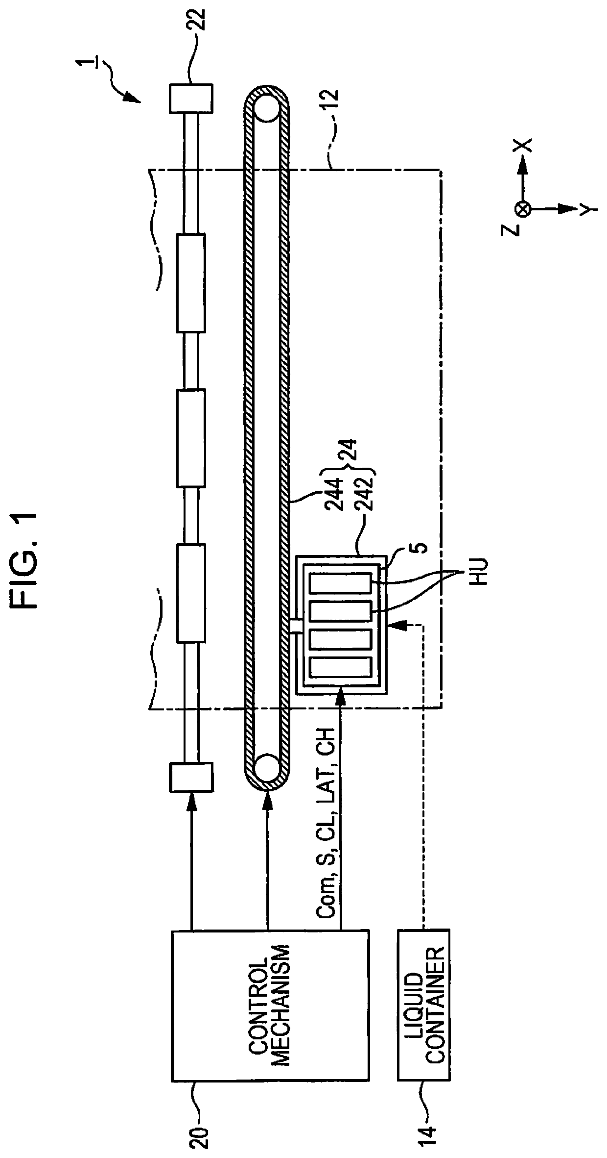
[0041]FIG. 1 is a configuration diagram showing the piezoelectric ink jet printer 1 according to the embodiment. The piezoelectric ink jet printer 1 according to the embodiment ejects ink, which is an example of liquid, to a medium 12 by driving a piezoelectric element. The medium 12 is typically printing paper; however, any printing object, such as a resin film, a fabric, or a color filter of an organic electroluminescence (EL) display may be used as the medium 12.

[0042]As shown in FIG. 1, the piezoelectric ink jet printer 1 includes a liquid container 14 that stores ink. The liquid container 14 may employ, for example, a cartridge attachable to and detachable from the piezoelectric ink jet printer 1, a bag-shaped ink pack formed of a flexible film, or an ink tank that can be replenished with ink. The liquid ...

first modification

[0141]While the change-signal generation circuit 721 is provided in the head driver DR in the above-described embodiment, the invention is not limited thereto, and the change signal CX may be supplied from the outside of the head driver DR.

second modification

[0142]While the waveform select signal SP is exemplified for the micro-vibration information for supplying the micro-vibration waveform PB to the piezoelectric element 37, the invention is not limited thereto, and the print signal SI may be used. In this case, it is presupposed that the print signal SI can designate non-vibration as an operation state of the ejection unit D, in addition to micro-vibration with which ink is not ejected. In this state, ink is not ejected and the driving signal Com is not supplied to the piezoelectric element 37. When the print signal SI indicates micro-vibration in the second period T2 in which the change signal CX is active, the micro-vibration controller 72 may replace the print signal SI indicting micro-vibration with the print signal SI indicating non-vibration, and may supply the print signal SI to the decoder circuit DC.


PUM


Abstract

A piezoelectric print head includes a piezoelectric element, a nozzle that ejects liquid when a piezoelectric element is driven, a transmission gate that switches between supply and non-supply of a driving signal for driving the piezoelectric element to the piezoelectric element, a micro-vibration controller that changes a waveform select signal supplied from outside and outputs the waveform select signal if a predetermined condition is satisfied, and a decoder circuit that controls ON / OFF of the transmission gate based on the waveform select signal output from the micro-vibration controller.

Description

[0001]This application claims priority to Japanese Patent Application No. 2017-186449 filed on Sep. 27, 2017. The entire disclosure of Japanese Patent Application No. 2017-186449 is hereby incorporated herein by reference.BACKGROUND[0002]1. Technical Field[0003]The present invention relates to a technology that uses a piezoelectric element for ejecting liquid such as ink.[0004]2. Related Art[0005]On-demand ink jet printers are roughly divided into thermal type that uses a heat generating element, and piezoelectric type that uses a piezoelectric element, as a driving element for ejecting liquid.[0006]The piezoelectric type is more advantageous than the thermal type because the piezoelectric type does not heat ink and hence can handle various kinds of ink, and can precisely control the ejection amount of ink. In the technical field of such a piezoelectric ink jet printer, there is known a print head having a thin-film piezoelectric developed through application of micro electro mechan...

Claims


Application Information

Patent Timeline
Patent Type & Authority Patents(United States)
IPC IPC(8): B41J2/045B41J2/14
CPCB41J2/04515B41J2/04588B41J2/04593B41J2/04581B41J2/04596B41J2/04573B41J2/14233B41J2/04541B41J2002/14491B41J2002/14241B41J2002/14362B41J2/04501
Inventor CHIKAMOTO, MOTONORI
Owner SEIKO EPSON CORP
Why Eureka
Try Eureka