
Outdoor heat exchanger

a heat exchanger and outdoor technology, applied in the field of outdoor heat exchangers, can solve the problems of increasing the energy requirements of electric vehicles, limiting the use of existing heating schemes, and inability to make defrosting well, so as to reduce the battery consumption of ev vehicles, secure the cooling performance, and maximally delay the frosting

Active Publication Date: 2020-04-21
HANON SYST
View PDF19 Cites 0 Cited by
  • Summary
  • Abstract
  • Description
  • Claims
  • Application Information

AI Technical Summary

Benefits of technology

The present invention relates to a heat pump system for vehicles that prevents non-uniform distribution of refrigerant and delays frosting to improve cooling performance. The outdoor heat exchanger has a down flow type structure that allows melted water to flow down during the defrosting process, improving the efficiency of the defrosting mode. The system can also include a flux distribution means to prevent the refrigerant from concentrating towards the rear side of the heat exchanger. The technical effects of the invention include maximizing the delay in frosting and reducing battery consumption, thereby increasing the driving distance of the electric vehicle.

Problems solved by technology

However, the vehicles increasingly require new energy sources due to various factors such as the environmental pollutions of the energy sources for vehicles and the reduction in oil deposits.
However, unlike the existing vehicles having an engine using petroleum as an energy source, electric vehicles may not use a heating system using cooling water.
However, since driving sources used in the electric vehicles do not generate heat as much as that generated from the engine, the electric vehicles have a limit of using the existing heating scheme.
The outdoor heat exchanger which is a cross flow type has a problem in that when fins / tubes are disposed, draining property of water melted during the defrosting process of melting frost is bad and thus the defrosting is not made well and the melted frost is re-frozen and thus the frosting occurs.
The reason is that since the gaseous refrigerant is changed to the liquefied refrigerant upon the cooling mode but the liquefied refrigerant is changed to the gaseous refrigerant upon the heating mode, when the same path is used, a flux distribution of a refrigerant is non-uniform inside a core and thus a non-generation area F of frosting occurs.

Method used


Image

  • Outdoor heat exchanger
  • Outdoor heat exchanger
  • Outdoor heat exchanger

Examples


Embodiment Construction

[0051]Hereinafter, an outdoor heat exchanger of a heat pump system for vehicles according to an exemplary embodiment of the present invention having the above-mentioned structure will be described in more detail with reference to the accompanying drawings.

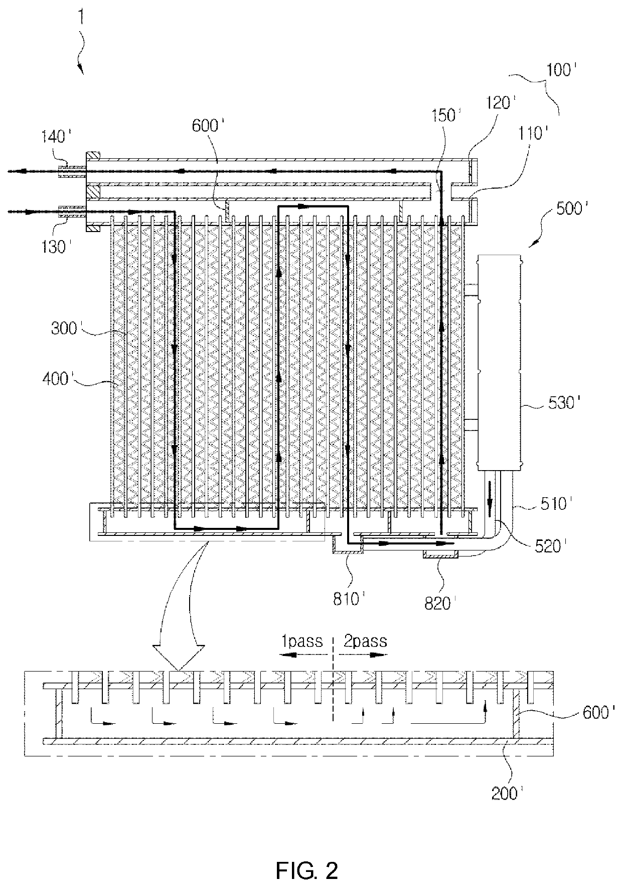
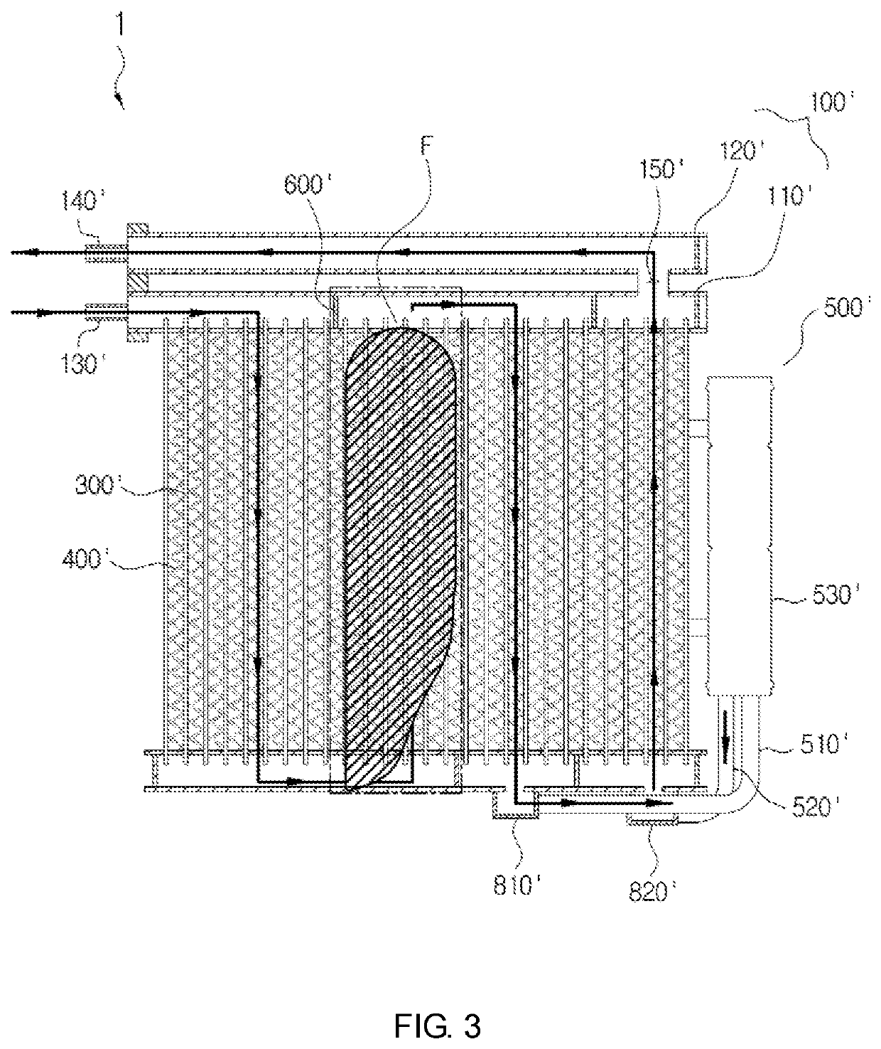
[0052]As illustrated in FIG. 4, an outdoor heat exchanger 1 according to an exemplary embodiment of the present invention serves as an evaporator upon a heating mode and a condenser upon a cooling mode in a heat pump system for vehicles, in which the existing condenser is formed in a down flow type and thus a refrigerant flows in a height direction.

[0053]The outdoor heat exchanger 1 according to the exemplary embodiment of the present invention is configured to largely include an upper tank 100, a lower tank 200, tubes 300, a liquid receiver 500, a baffle 600, and a flux distribution means 700 or a flux distribution plate.

[0054]The upper tank 100 and the lower tank 200 are formed to extend in a length direction and are provided in ...


PUM


Abstract

The present invention relates to an outdoor heat exchanger, and more particularly, to a down flow type outdoor heat exchanger having channels of at least three paths in a heat pump system for vehicles, in which a flux distribution means protruded in a height direction is further formed in a lower tank in which the channel is changed from an upward direction to a downward direction or from a downward direction to an upward direction to block some area of a lower portion thereof so as to prevent a refrigerant from being non-uniformly distributed while a flux is concentrated toward a rear side of the channel due to a fluid inertia in an area in which the flow path is changed, thereby delaying frosting upon heating.

Description

CROSS-REFERENCE TO RELATED APPLICATIONS[0001]This patent application is a United States national phase patent application based on PCT / KR2015 / 004390 filed Apr. 30, 2015 which claims the benefit of Korean Patent Application No. 10-2014-0059852 filed May 19, 2014. The entire disclosures of the above patent applications are hereby incorporated herein by reference.TECHNICAL FIELD[0002]The present invention relates to an outdoor heat exchanger, and more particularly, to a down flow type outdoor heat exchanger having channels of at least three paths in a heat pump system for vehicles, in which a flux distribution means protruded in a height direction is further formed in a lower tank in which the channel is changed from an upward direction to a downward direction or from a downward direction to an upward direction to block some area of a lower portion thereof so as to prevent a refrigerant from being non-uniformly distributed while a flux is concentrated toward a rear side thereof due to ...

Claims


Application Information

Patent Timeline
Patent Type & Authority Patents(United States)
IPC IPC(8): B60H1/00F28F9/013F25B39/04F25B13/00F25B5/04F25B40/00F25B6/04
CPCF25B13/00F25B39/04F28F9/013B60H1/00335F25B5/04F25B2339/044F25B2400/0411F25B2341/0662F25B6/04F25B40/00F25B2400/0409F28D1/05375F28F9/0204F28F9/0212F28F9/028F25B41/39
Inventor SONG, JUN YOUNGLIM, HONG-YOUNGOH, KWANG HUN
Owner HANON SYST
Learn More