
Electrosurgical forceps for video assisted thoracoscopic surgery and other surgical procedures

a technology of thoracoscopic surgery and forceps, applied in the field of surgical instruments, can solve the problems of limited thoracic cavity, limited thoracic cavity maneuverability, and limited access to the thoracic cavity, and achieve the effect of reducing the force necessary

Active Publication Date: 2020-04-28
TYCO HEALTHCARE GRP LP
View PDF490 Cites 1 Cited by
  • Summary
  • Abstract
  • Description
  • Claims
  • Application Information

AI Technical Summary

Benefits of technology

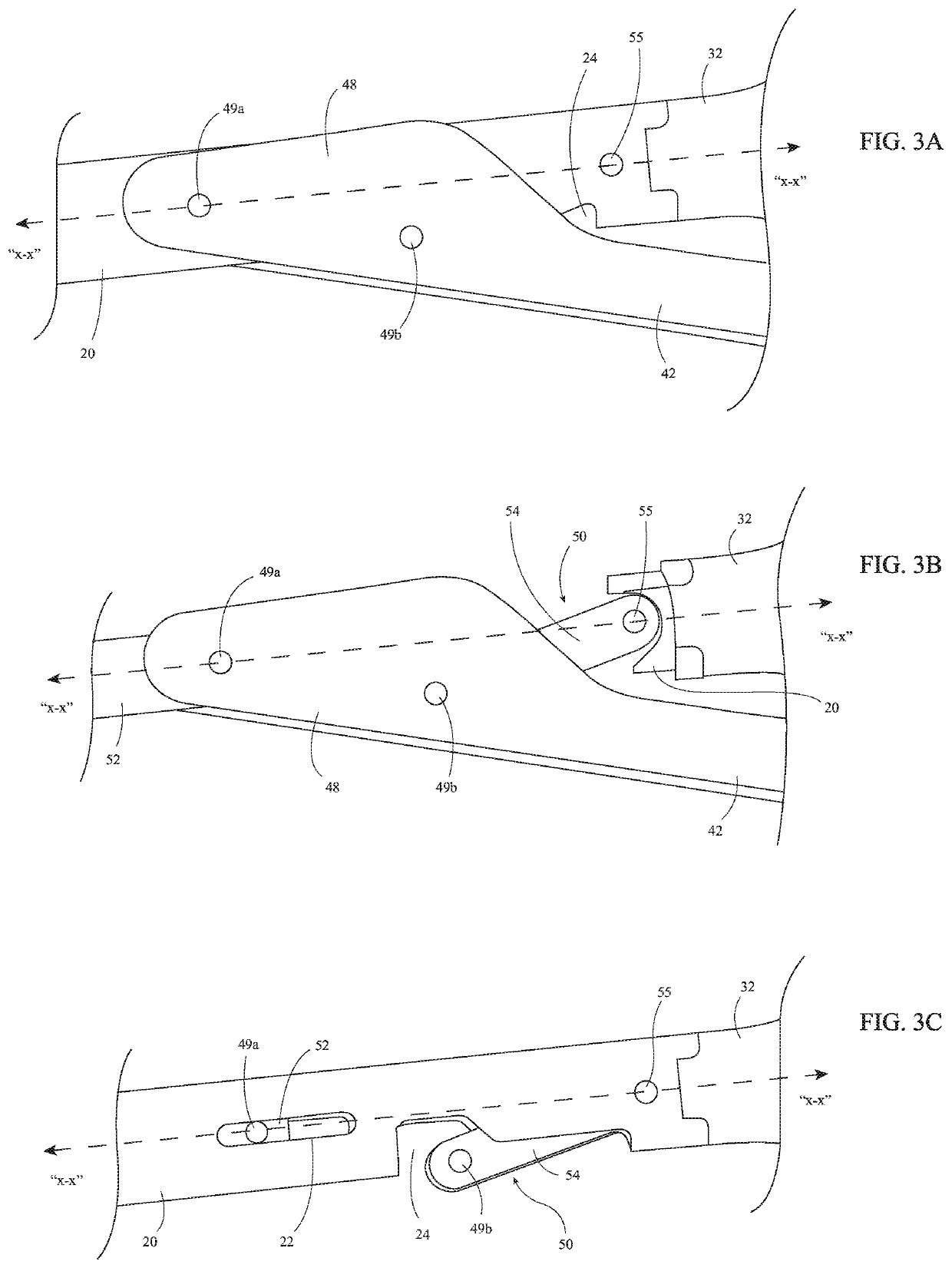
[0008]In accordance with aspects of the present disclosure, a surgical instrument is provided. The surgical instrument includes an elongated shaft defining a longitudinal axis and including a proximal portion and a distal portion, an end effector assembly coupled to the distal portion of the elongated shaft, a fixed handle coupled to the proximal portion of the elongated shaft, a drive bar, a movable handle, and a linkage. The drive bar is slidably disposed within the elongated shaft and operably coupled to the end effector assembly such that translation of the drive bar through the elongated shaft manipulates the end effector assembly. The movable handle is movable relative to the fixed handle between an open position and a closed position to translate the drive bar through the elongated shaft. The movable handle, more specifically, is pivotably coupled to the drive bar via a first pivot pin. The first pivot pin is aligned on the longitudinal axis. The linkage includes a first end portion and a second end portion. The first end portion of the linkage is pivotably coupled to the movable handle via a second pivot pin, while the second end portion of the linkage is pivotably coupled to the elongated shaft via a third pivot pin. The third pivot pin is aligned on the longitudinal axis. In the closed position of the movable handle, the second pivot pin is disposed in a near-over-center position relative to the longitudinal axis to reduce a force necessary to maintain the movable handle in the closed position.
[0019]Another surgical instrument provided in accordance with aspects of the present disclosure includes an elongated shaft, an end effector assembly, a drive bar, a movable handle, and a linkage. The elongated shaft includes a proximal portion and a distal portion. The end effector assembly is coupled to the distal portion of the elongated shaft and includes first and second jaw members movable between a spaced-apart position and an approximated position. The drive bar is slidably disposed within the elongated shaft and operably coupled to the first jaw member and / or the second jaw member such that translation of the drive bar through the elongated shaft moves the first and second jaw members between the spaced-apart position and the approximated position. The movable handle is pivotably coupled to the drive bar via a first pivot pin and is movable between an open position and a closed position to translate the drive bar through the elongated shaft to thereby move the first and second jaw members between the spaced-apart position and the approximated position. The linkage includes a first end portion and a second end portion. The first end portion of the linkage is pivotably coupled to the movable handle via a second pivot pin. The second end portion of the linkage is pivotably coupled to the elongated shaft via a third pivot pin. In the closed position of the movable handle, the second pivot pin is disposed in a near-over-center position relative to the first pivot pin and the third pivot pin to reduce a force necessary to maintain the movable handle in the closed position.

Problems solved by technology

In minimally-invasive thoracic surgery, for example, access to the thoracic cavity as well as maneuverability within the thoracic cavity is limited since the access port is typically placed within the confined intercostal space between a patient's ribs.

Method used


Image

  • Electrosurgical forceps for video assisted thoracoscopic surgery and other surgical procedures
  • Electrosurgical forceps for video assisted thoracoscopic surgery and other surgical procedures
  • Electrosurgical forceps for video assisted thoracoscopic surgery and other surgical procedures

Examples


Embodiment Construction

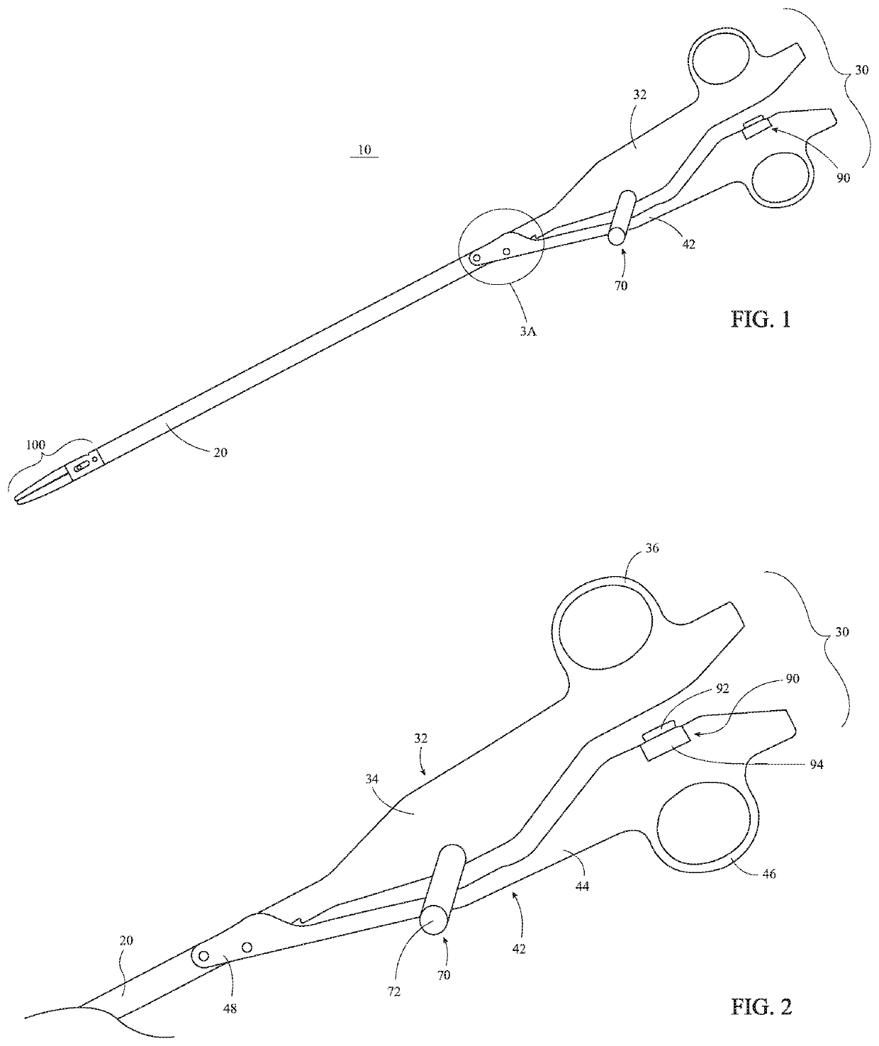
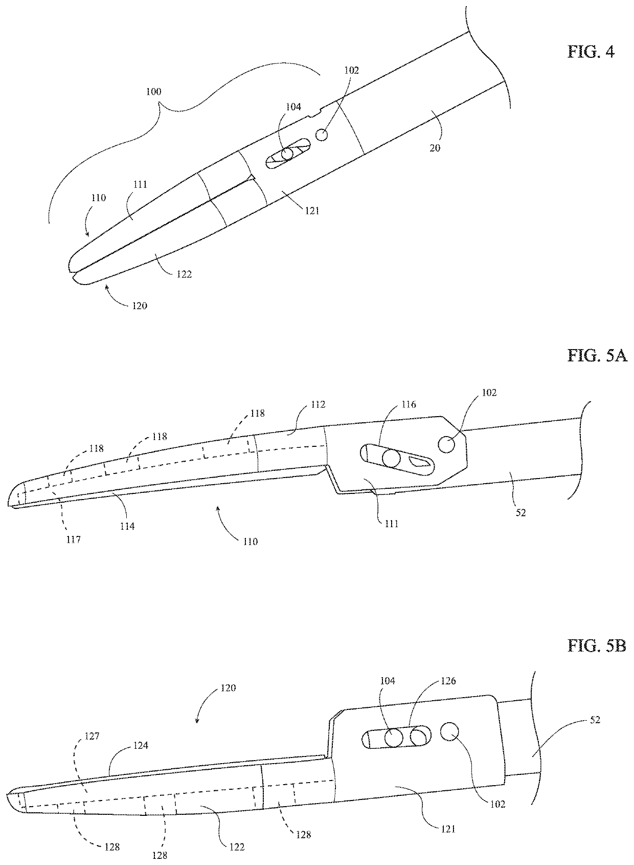
[0044]Turning to FIG. 1, an electrosurgical forceps provided in accordance with the present disclosure is shown generally identified by reference numeral 10. Forceps 10 is configured for use in VATS procedures and other surgical procedures and generally includes an elongated shaft 20, a handle assembly 30, a drive assembly 50 (FIGS. 3A-3C), a trigger assembly 70, a knife assembly 80 (FIGS. 8 and 9), an activation assembly 90, and an end effector assembly 100 which mutually cooperate to grasp, treat, and / or cut tissue. Forceps 10 further includes an electrosurgical cable (not shown) adapted to connect forceps 10 to a source of energy, e.g., a generator (not shown), although forceps 10 may alternatively be configured as a battery-powered instrument.

[0045]With additional reference to FIG. 2, handle assembly 30 is operably coupled to a proximal portion of elongated shaft 20 and includes a pair of handle members: a fixed handle 32 and a movable handle 42. Fixed handle 32 is fixedly engag...


PUM


Abstract

A surgical instrument includes a shaft defining an axis, an end effector coupled to a distal portion thereof, a fixed handle coupled to a proximal portion thereof, a drive bar, a movable handle, and a linkage. The drive bar is disposed within the shaft and operably coupled to the end effector. The movable handle is movable relative to the fixed handle between open and closed positions and is coupled to the drive bar via a first pin on the axis. The linkage includes a first end portion coupled to the movable handle via a second pin and a second end portion coupled to the shaft via a third pin on the axis. In the closed position of the movable handle, the second pin is disposed in a near-over-center position relative to the axis to reduce a force necessary to maintain the movable handle in the closed position.

Description

CROSS REFERENCE TO RELATED APPLICATION[0001]The present application claims the benefit of and priority to U.S. Provisional Application Ser. No. 62 / 374,989, filed on Aug. 15, 2016 the entire contents of which are incorporated herein by reference.BACKGROUNDTechnical Field[0002]The present disclosure relates to surgical instruments and, more particularly, to an electrosurgical forceps configured for treating and / or cutting tissue in Video Assisted Thoracoscopic Surgery and other surgical procedures.Background of Related Art[0003]In minimally-invasive surgical procedures, operations are carried out within the body by elongated instruments inserted through small entrance openings in the body, either directly or through one or more access ports positioned within the entrance openings. Because the instrumentation and any required punctures or incisions are relatively small, minimally-invasive surgery is less invasive compared to conventional open surgical procedures. As a result, minimally...

Claims


Application Information

Patent Timeline
Patent Type & Authority Patents(United States)
IPC IPC(8): A61B17/32A61B34/35A61B17/29A61B34/30A61B17/00
CPCA61B17/320016A61B17/00234A61B17/2909A61B2034/302A61B34/35A61B2017/2946A61B18/1445A61B2018/00922A61B2017/2936A61B17/2804A61B2017/2922A61B18/085
Inventor FRUSHOUR, SCOTT E. M.LARSON, ERIC R.
Owner TYCO HEALTHCARE GRP LP
Learn More