Eureka AIR delivers breakthrough ideas for toughest innovation challenges, trusted by R&D personnel around the world.

Distributer phase shifter for a hydraulic pump motor

a technology of hydraulic pump motor and distributor, which is applied in the direction of rotary piston engines, vehicle components, rotary or oscillating piston engines, etc., can solve the problems of difficult or even impossible in practice to vary the angular sector occupied by input-output angular collectors, difficult or even impossible in the field of distribution phase shifters, and achieve the effect of moderate manufacturing cost pri

Active Publication Date: 2020-04-28
RABHI VIANNEY
View PDF28 Cites 0 Cited by
  • Summary
  • Abstract
  • Description
  • Claims
  • Application Information

AI Technical Summary

Benefits of technology

[0016]Moreover, the distributor phase shifter for a hydraulic pump motor according to the invention is provided to be integrated in the pump motor according to the U.S. Pat. No. 3,001,775 without jeopardizing the feasibility of this pump motor at a moderate manufacturing cost price and without having to use any realization process that is complex or uses expensive material.

Problems solved by technology

In fact, this compressibility brings about non-recoverable work losses when there is a significant separation of pressure between on the one hand an internal canal of input-output of the central rotor connected to a hydraulic cylinder and on the other hand the input-output angular collector of the internal or external conduit at the moment at which this internal canal is placed in rotation via its input-output orifice of the central rotor with this collector.
Unfortunately, it is difficult or even impossible in practice to vary the angular sector occupied by the input-output angular collectors of the external conduit just as it is difficult or even impossible to vary the angular position of each of these collectors relative to the pump motor housing independently of each other.

Method used


Image

  • Distributer phase shifter for a hydraulic pump motor
  • Distributer phase shifter for a hydraulic pump motor
  • Distributer phase shifter for a hydraulic pump motor

Examples


Embodiment Construction

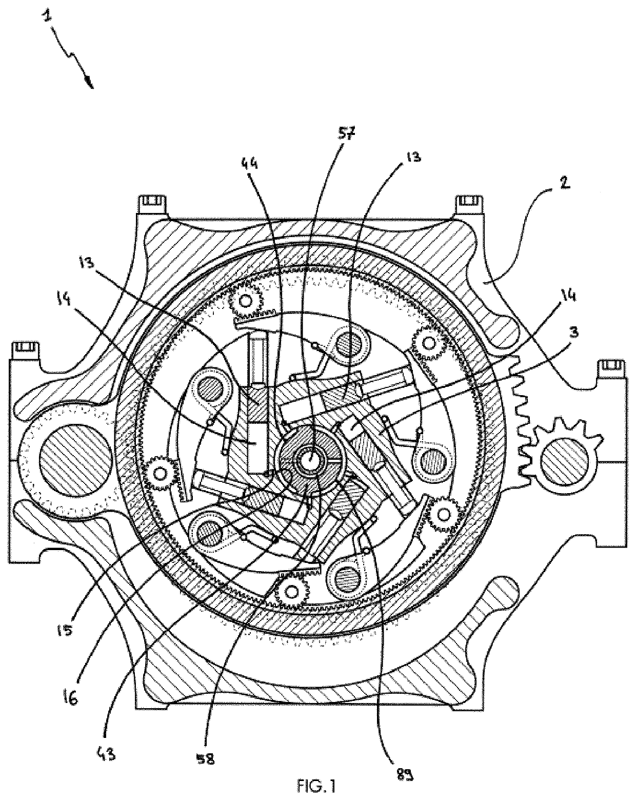
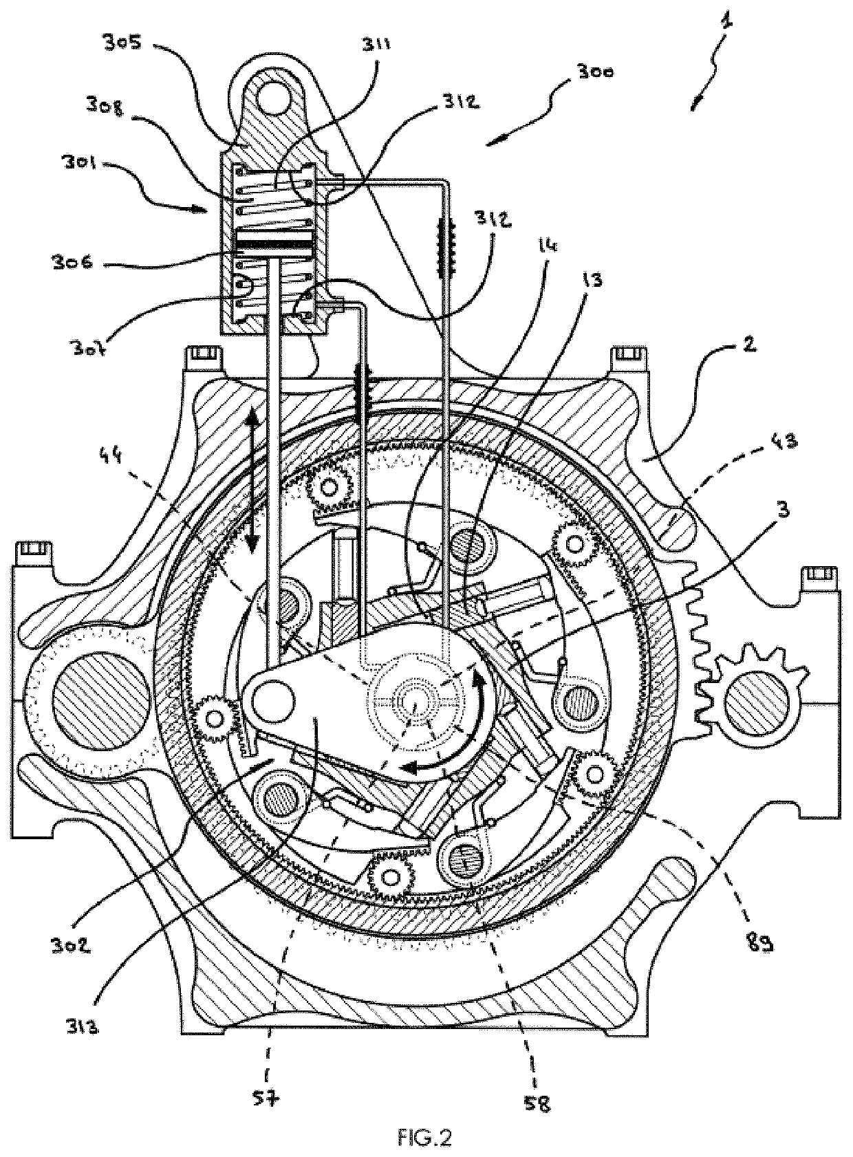
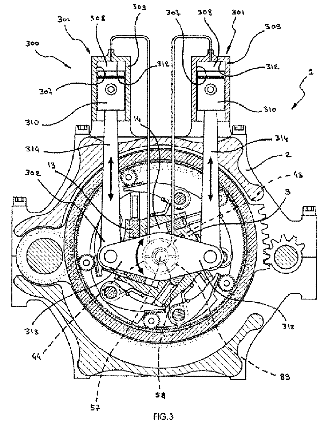
[0036]FIGS. 1 to 6 showed the distributor phase shifter for a hydraulic pump motor 300, various details of its components, its variants and its accessories.

[0037]The distributor phase shifter for a hydraulic pump motor 300 is provided for a hydraulic pump motor 1 such as is shown in FIG. 1 and which comprises a motor pump housing 2 on the one hand and a motor pump central rotor 3 on the other hand, which latter houses at least one hydraulic cylinder 14 in which a hydraulic piston 13 can move in translation, which central rotor 3 cooperates with an input-output distributor 43 which presents it with an input-output angular collector of internal conduit 44 and with an input-output angular collector of external conduit 89 in such a manner that when this rotor 3 rotates relative to the housing of pump motor 2, the hydraulic cylinder 14 is alternately put in relationship—via an input-output internal canal of central rotor 15, then by an input-output orifice of central rotor 16—with an inp...


PUM


Abstract

The distributor phase shifter for a hydraulic pump motor (300) is provided for a hydraulic pump motor (1) which includes a pump motor housing (2) and a pump motor central rotor (3) to which an input-output distributor (43) presents an input-output angular collector of an internal conduit (44) and an input-output angular collector of an external conduit (89), which phase shifter includes a phase shift acting element (301) which is supported on the housing of the pump motor (2) in order to make the input-output distributor (43) rotate around its longitudinal axis and over a determined angular range.

Description

FIELD OF THE INVENTION[0001]The present invention relates to a distributor phase shifter for a hydraulic pump motor that constitutes an improvement of the hydraulic pump motor constituting the subject of the French patent application No. 3 001775 dated May 22, 2013 belonging to the applicant.BACKGROUND OF THE INVENTION[0002]The hydraulic pump motor forming the subject of this application comprises a central rotor of the pump motor inside of which hydraulic cylinders are arranged. Hydraulic pistons can move inside these cylinders. When the central rotor rotates relative to the housing of the pump motor, these cylinders are alternately put in a relationship with an internal input-output conduit, then with an external input-output conduit by an input-output distributor constituted either by a cylindrical stator or by an axial stator. To this end this distributor has an internal input-output conduit angular collector central to this rotor which is connected to the internal input-output ...

Claims


Application Information

Patent Timeline
Patent Type & Authority Patents(United States)
IPC IPC(8): F01C20/10F01C1/38F01C1/344F01C21/08F01C21/10F04C14/10F04C2/344F04B9/10B60K6/12F03C1/40F03C1/30
CPCF04B9/10F03C1/0409B60K6/12F03C1/045F03C1/0466
Inventor RABHI, VIANNEY
Owner RABHI VIANNEY
Why Eureka
Eureka Blog
Learn More