Transparent screen and image display system

a technology of transparent screen and image display, applied in the direction of projectors, polarising elements, instruments, etc., can solve the problems of high transparency hot spot to occur, etc., and achieve the effect of reducing hot spot caused by transmitted light and high transparency

Active Publication Date: 2020-05-05
FUJIFILM CORP
View PDF33 Cites 0 Cited by
  • Summary
  • Abstract
  • Description
  • Claims
  • Application Information

AI Technical Summary

Benefits of technology

[0009]That is, in an image display system including a transparent screen, it is desired to develop a transparent screen in which high transparency is secured and a hot spot caused by transmitted light is reduced.
[0010]An object of the present invention is to solve the above-described problem of the related art and to provide a transparent screen having high transparency in which a hot spot caused by transmitted light can be reduced, and an image display system including the transparent screen.
[0011]As a result of thorough investigation for achieving the object, the present inventors found that the object can be achieved by providing a first λ / 4 plate, a reflecting layer that has a structure obtained by immobilizing a cholesteric liquid crystalline phase and reflects a part of incidence light, and a polarizing film that has an absorption axis in a thickness direction in this order, thereby completing the present invention.
[0030]According to the present invention, it is possible to realize: a transparent screen having high transparency in which a hot spot caused by transmitted light can be reduced; and an image display system including the transparent screen in which a hot spot caused by transmitted light is reduced

Problems solved by technology

However, in a case where an image is displayed using a projector, there is a problem in that a hot spot occurs.
In particular, in a laser projector in which a transparent screen is used and a laser is used as a light source, a hot spot is extremely glaring.
In a typical opaque screen, specularly reflected light in a straight advancing direction of outgoing light of a projector causes a hot spot to occur.
However, in the transparent screen described in JP1993-107660A (JP-H5-107660A), in a case where the uneven structure is imparted to the outermost surface, the transparency significantly deteriorates, and thus a countermeasure thereagainst cannot be used.

Method used


Image

  • Transparent screen and image display system
  • Transparent screen and image display system
  • Transparent screen and image display system

Examples


example 1

[0364]

[0365]Components shown below were stirred and dissolved in a container held at 25° C. to prepare an underlayer-forming solution.

[0366](Underlayer-Forming Solution)

[0367]Mixture A of the following rod-shaped liquid crystal compounds: 100 parts by mass

[0368]IRGACURE 819 (manufactured by BASF SE): 3 parts by mass

[0369]The following compound A: 0.6 parts by mass

[0370]Methyl ethyl ketone: 932.4 parts by mass

[0371]Mixture A of the following rod-shaped liquid crystal compounds

[0372]

[0373]Numerical values are represented by mass %. In addition, R represents a group to be bonded to oxygen.

[0374]

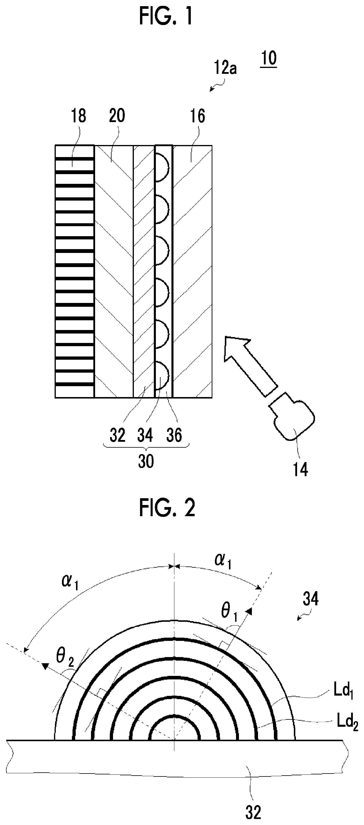
[0375]As the support 32, a transparent PET film (COSMOSHINE A4100, manufactured by Toyobo Co., Ltd.) having a thickness of 75 μm was prepared.

[0376]The prepared underlayer-forming solution was applied to the support 32 using a bar coater #2.6. Next, the coating film was heated such that the coating film surface temperature was 50° C., and then was dried for 60 seconds. Next, in a nitrogen purged...


PUM

PropertyMeasurementUnit
angleaaaaaaaaaa
angleaaaaaaaaaa
angleaaaaaaaaaa

Abstract

Provided are a transparent screen having high transparency in which a hot spot caused by transmitted light can be reduced; and an image display system in which visibility of a screen is excellent and a hot spot is reduced by using the transparent screen. The transparent screen includes, in this order: a first λ / 4 plate; a reflecting layer that has a structure obtained by immobilizing a cholesteric liquid crystalline phase and reflects a part of incidence light; and a polarizing film that has an absorption axis in a thickness direction.

Description

CROSS-REFERENCE TO RELATED APPLICATIONS[0001]This application is a Continuation of PCT International Application No. PCT / JP2017 / 016281 filed on Apr. 25, 2017, which claims priority under 35 U.S.C. § 119(a) to Japanese Patent Application No. 2016-092451 filed on May 2, 2016. The above application is hereby expressly incorporated by reference, in its entirety, into the present application.BACKGROUND OF THE INVENTION1. Field of the Invention[0002]The present invention relates to a transparent screen and an image display system including this transparent screen.2. Description of the Related Art[0003]Recently, as a screen constituting a projection type display device, a transparent screen that diffuses and / or reflects projection light projected from a projector to display an image and allows transmission of light from front and back surfaces is known.[0004]For example, JP1993-107660A (JP-H5-107660A) describes a projection type liquid crystal projection system including a transparent scre...

Claims


Application Information

Patent Timeline
Patent Type & Authority Patents(United States)
IPC IPC(8): G03B21/62G02B27/09G03B21/604G02B5/02G02B5/30
CPCG03B21/604G02B5/3016G02B5/0294G02B5/30G02B27/0977G03B21/62G02B5/3025G02B5/3083
Inventor YANAI, YUJIRONAGAI, MICHIOYAMAMOTO, AKIRA
Owner FUJIFILM CORP
Why Eureka
Try Eureka