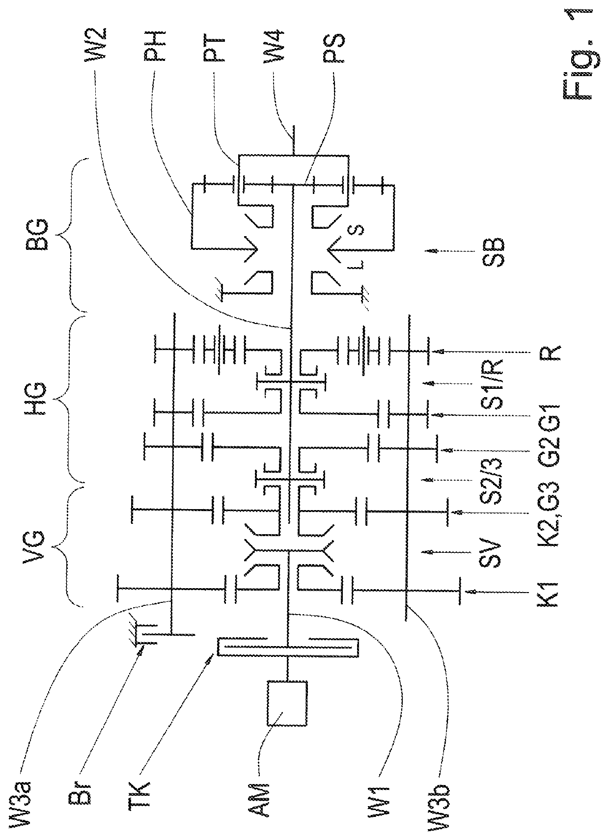
[0009]The invention now comprises the technical teachings that the transmission brake is actuated for supporting the synchronization of the front-mounted group on the basis of a prevailing driving or operating situation. In other words, the actuation of the transmission brake for supporting the synchronization of the front-mounted group is only effected if doing so is necessary or useful due to a prevailing driving or operating situation. The number of actuations of the transmission brake and the resulting wear on the transmission brake are thus kept low. For example, the transmission brake can be configured as a hydraulically or pneumatically actuatable multiple-disc brake. The transmission brake can also be configured as an electric motor, via which a braking torque can be applied to a transmission shaft of the range-change transmission for supporting the synchronization of the front-mounted group in the course of an upshift in the range-change transmission. For example, if the transmission brake is configured as pneumatically or hydraulically actuatable via shift valves, then the number of actuations of the shift valves can also be kept correspondingly small. By virtue of the actuation of the transmission brake, not only the front-mounted group but also the main transmission can be synchronized faster.
[0010]Specifically when it is cold, the drag torque of the range-change transmission increases significantly. Due to the increased drag torque of the range-change transmission, a speed reduction occurs considerably faster during the synchronization of the front-mounted group when the main transmission is in the neutral position than in a synchronization of the front-mounted group carried out at the operating temperature of the transmission. Consequently, actuation of the transmission brake in such an operating situation would not lead to any substantial support of the synchronization of the front-mounted group, thus the shifting time for the upshift would also not be shortened at all or not substantially. In a variant of the method according to the invention, provision is therefore made such that the transmission brake is actuated for supporting the synchronization of the front-mounted group if a transmission fluid temperature is higher than a threshold defined for the transmission fluid temperature. Hence the transmission brake can be actuated for supporting the synchronization of the front-mounted group if the transmission fluid temperature reaches or exceeds a threshold of, for example, 20° C. Unnecessary actuation of the transmission brake at lower transmission fluid temperatures can thus be avoided.
[0011]According to a further variant of the method of the invention, provision is made such that the transmission brake is actuated for supporting the synchronization of the front-mounted group if a speed of the drive engine is higher than a threshold specified for the engine speed. Thus the transmission brake can be actuated for supporting the synchronization of the front-mounted group if the speed of the drive engine reaches or exceeds a threshold of, for example, 1500 rpm, wherein upshifts can then be achieved within short shifting times. At lower engine speeds on the other hand, the front-mounted group is synchronized only via the synchronization elements of the clutch of the front-mounted group.
[0012]According to another variant of the method according to the invention, provision is made such that the transmission brake is actuated for supporting the synchronization of the front-mounted group if a current driving resistance reaches or exceeds a specified threshold. If the current driving resistance is below the specified threshold, the upshift can then be effected more slowly without actuating the transmission brake, because the synchronization of the front-mounted group can be effected solely via the mechanical synchronization elements of the clutch of the front-mounted group in order to reach the necessary shifting time. On the other hand, if the current driving resistance reaches or exceeds the specified threshold, then during an upshift in the range-change transmission, the transmission brake is actuated for supporting the synchronization of the front-mounted group actuated upon upshifting. The shifting time necessary for the upshift and hence an interruption of the traction force occurring while upshifting can thus be shortened.
[0016]A further variant of the method of the invention makes provision such that the transmission brake is actuated for supporting the synchronization of the front-mounted group if a current driver input in the form of an accelerator pedal actuation reaches or exceeds a specified threshold. Thus provision can be made such that, for example, synchronization of the front-mounted group is supported by actuation of the transmission brake in the event of accelerator pedal actuation within a range of 70% to 100% of the maximum possible accelerator pedal actuation. Short shifting times thus achieved are advantageous in a driving situation with a high level of driver input and high vehicle acceleration associated therewith.
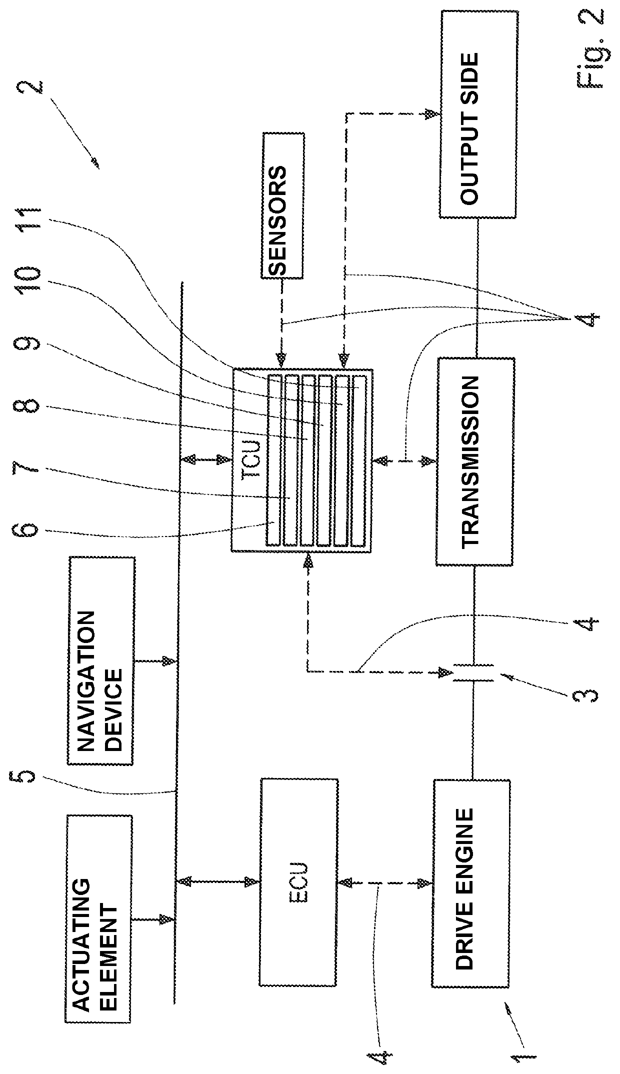
[0019]If it is determined by means of the predictive route data that the motor vehicle will soon no longer be on a road, i.e., will be operating off-road, or that a steep gradient lies directly ahead of the motor vehicle, then upon reaching the section of the route thus identified, a shifting strategy will be employed in which the transmission brake will be actuated for synchronizing the front-mounted group in the course of an upshift. Upshifts with short shifting times are advantageous in identified situations such as these.

