Measuring device for acquiring measurement values for measuring a tension in a conveying system, as well as a conveying unit and a conveying facility

a technology of conveying system and measurement device, which is applied in the direction of tension measurement, force/torque/work measurement apparatus, instruments, etc., can solve the problem of not being able to obtain a continuous measurement of the tension of the conveying member

Active Publication Date: 2020-05-19
FERAG AG
View PDF21 Cites 7 Cited by
  • Summary
  • Abstract
  • Description
  • Claims
  • Application Information

AI Technical Summary

Benefits of technology

[0012]The tension, which is determined in such a manner, is hereinafter designated as the measured tension. The tension of the conveying member can be closed-loop controlled with the measured tension, so that it is compensated over the complete length of the conveying member. In particular, it can be closed-loop controlled such that as a whole an as small as possible force is exerted upon the conveying member by way of one or more drives that engage on the conveying member—just enough force to keep it in motion. The mechanical loading of the conveying member is minimised by this, which in turn reduces its wear and increases the service life. Furthermore, the drive energy is kept small and is at least approximately minimised.
[0027]Such contact-free measuring transducers are low in maintenance, robust and insensitive to contamination. They have a high durability with regard to long-term alternating loads.

Problems solved by technology

However, with this it is not possible to obtain a continuous measurement of the tension of the conveying member at a certain location of the conveying track.

Method used


Image

  • Measuring device for acquiring measurement values for measuring a tension in a conveying system, as well as a conveying unit and a conveying facility
  • Measuring device for acquiring measurement values for measuring a tension in a conveying system, as well as a conveying unit and a conveying facility
  • Measuring device for acquiring measurement values for measuring a tension in a conveying system, as well as a conveying unit and a conveying facility

Examples


Embodiment Construction

[0048]Basically, the same parts are provided with the same reference numerals in the figures.

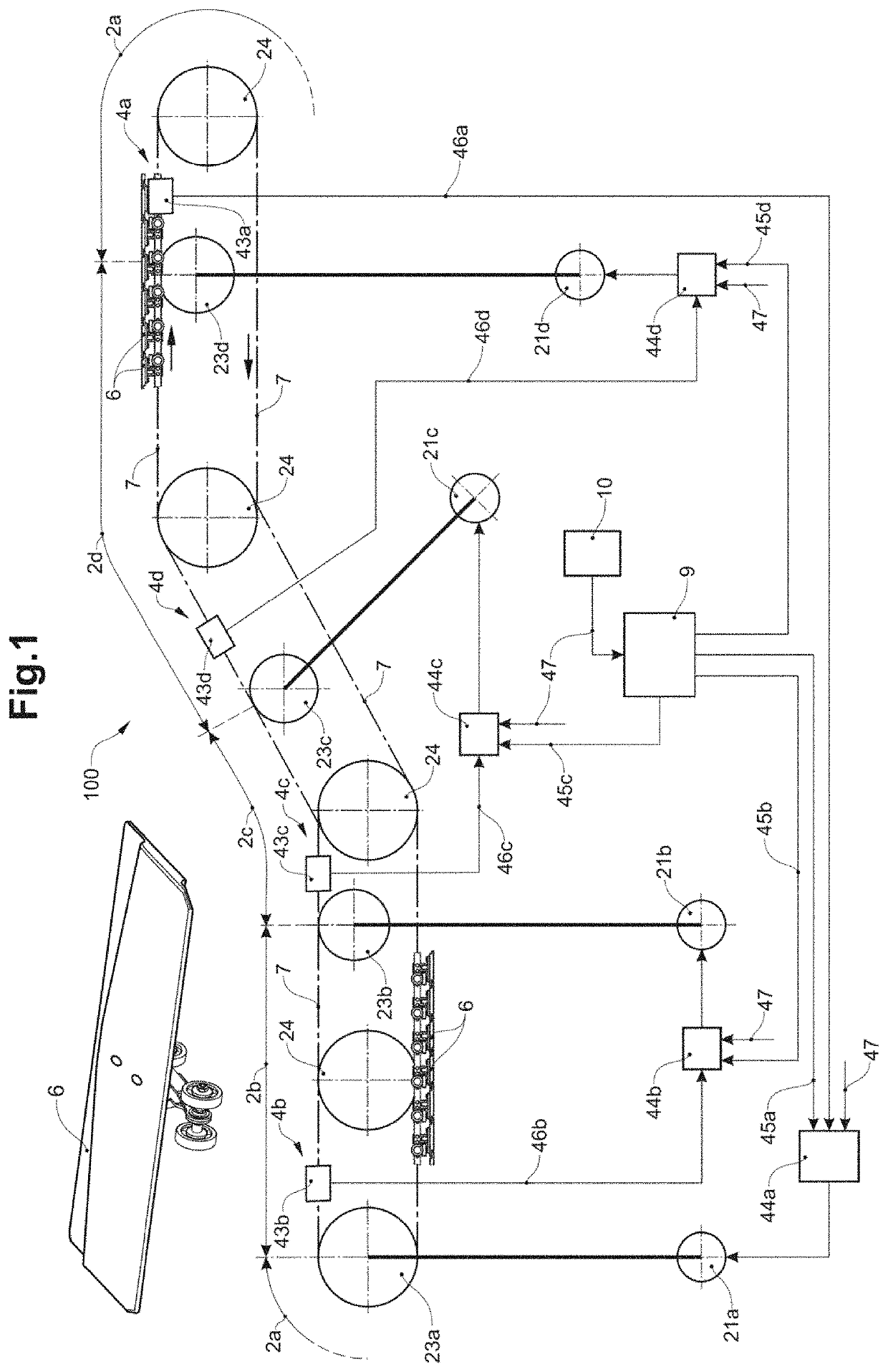
[0049]FIG. 1 shows a conveying system 100 with a circulating conveying member 7, which is driven by several drives 21a, 21b, 21c, 21d, by which means conveying sections 2a, 2b, 2c, 2d, which lie between the drives, are defined. The conveying member 7 is a circulating conveying member with, for example, plate elements as conveying links 6, which are concatenated or interlinked to one another, or are pulled by way of a pulling means. The conveying member 7, guided by way of co-running, non-driven rollers 24, some of which are also deflecting rollers, runs in a guided manner around its circulating path (whose course is represented schematically by dot-dashed lines). Devices for force introduction 23a, 23b, 23c, 23d, which drive the conveying member, are arranged at several locations of the circulating track. These, for example, are cogs or cam wheels. These act, for example, in a deflecting dri...


PUM

PropertyMeasurementUnit
tensile forcesaaaaaaaaaa
tensionaaaaaaaaaa

Abstract

A measuring device serves for acquiring measurement values for measuring a tension in a conveying system. The measuring device is designed to guide a conveying member from a first section of the measuring device to a second section of the measuring device, to effect a deflection of the conveying member with regard to a straight-lined connection between the first and the second section and to detect measurement values corresponding to a reaction force according to this deflection. The measuring device includes surfaces for guiding rollers of the conveying member. One of these surfaces is a deflecting surface for deflecting the conveying member. The deflecting surface is formed on a deflecting element of a measuring element, and the reaction force is a force which acts upon the measuring element.

Description

BACKGROUND OF THE INVENTIONField of the Invention[0001]The invention generally relates to the field of conveying technology and, more particularly, to a measuring device for acquiring measurement values for measuring a tension in a conveying system, to a conveying unit and to a conveying facility.Description of Related Art[0002]Long conveying units, even over kilometres, for example as part of sorting conveyers, can be present in logistics facilities. They can be subjected to changing loads and be led upwards and downwards. Several drives can be arranged along a conveying unit for the drive of accordingly long conveying members, for example with concatenated (or interlinked) conveying links. The drive forces that are exerted upon the conveying member by these drives must be coordinated with one another, so that on the one hand the conveying member is moved at the necessary conveying speed and on the other hand locally high loading does not occur, such loading in the extreme case bei...

Claims


Application Information

Patent Timeline
Patent Type & Authority Patents(United States)
IPC IPC(8): B65G43/00G01L5/04B65G17/06G01L5/107B65G43/06B65G43/02
CPCB65G43/00G01L5/107G01L5/04B65G17/065B65G43/02B65G17/30G01L1/08G01L5/06B65G43/10
Inventor MÄDER, CARL CONRAD
Owner FERAG AG
Why Eureka
Try Eureka