

Projection display unit
a technology of projection display and display unit, which is applied in the field of projection display unit, can solve the problems of reducing the s/n ratio in some cases, and deteriorating the image quality of captured images
Active Publication Date: 2020-05-19
SONY CORP
View PDF23 Cites 4 Cited by
- Summary
- Abstract
- Description
- Claims
- Application Information
AI Technical Summary
Benefits of technology
The patent text describes a projection display unit that improves image quality by preventing degradation in captured images. This is achieved by separating the polarization component emitted from the illumination section and the component to be detected in the light-receiving section, making it possible to share a projection lens. The light valve modulates and projects the illumination onto the projection surface, while the light-receiving section reads object information on the surface. However, a portion of the light emitted from the illumination section may leak into the light-receiving section, deteriorating the signal-to-noise ratio in the captured image. To address this, the projection lens has a pupil range assigned for projection, and the light-receiving section includes a light-shielding part that blocks the leaked light and inhibits it from reaching the imaging device, resulting in a higher signal-to-noise ratio and improved image quality.
Problems solved by technology
In the above-described projection display unit, however, a portion of light emitted from the illumination section leaks into light-receiving side, and thus lowers an S / N ratio in some cases.
This leads to degradation in image quality of a captured image.
Method used
View moreImage
Smart ImageViewing Examples

Examples
first embodiment (
1. First Embodiment (A projection display unit in which a projection lens section is subjected to pupil division and a light-shielding member is disposed at an aperture position of a relay optical system of a light-receiving section)
second embodiment (
2. Second Embodiment (A projection display unit in which a light-shielding mask and a lens are disposed for each pixel on a light-shielding surface of an imaging device in a light-receiving section)
modification example 1 (
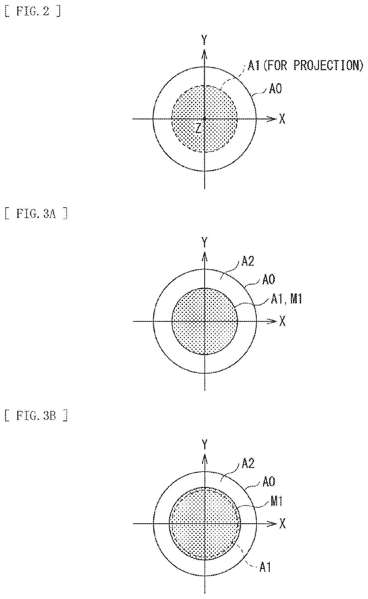
3. Modification Example 1 (Another example of pupil division: an example in which a middle part is used for imaging and a circumferential part is used for projection)
Login to View More PUM
 Abstract
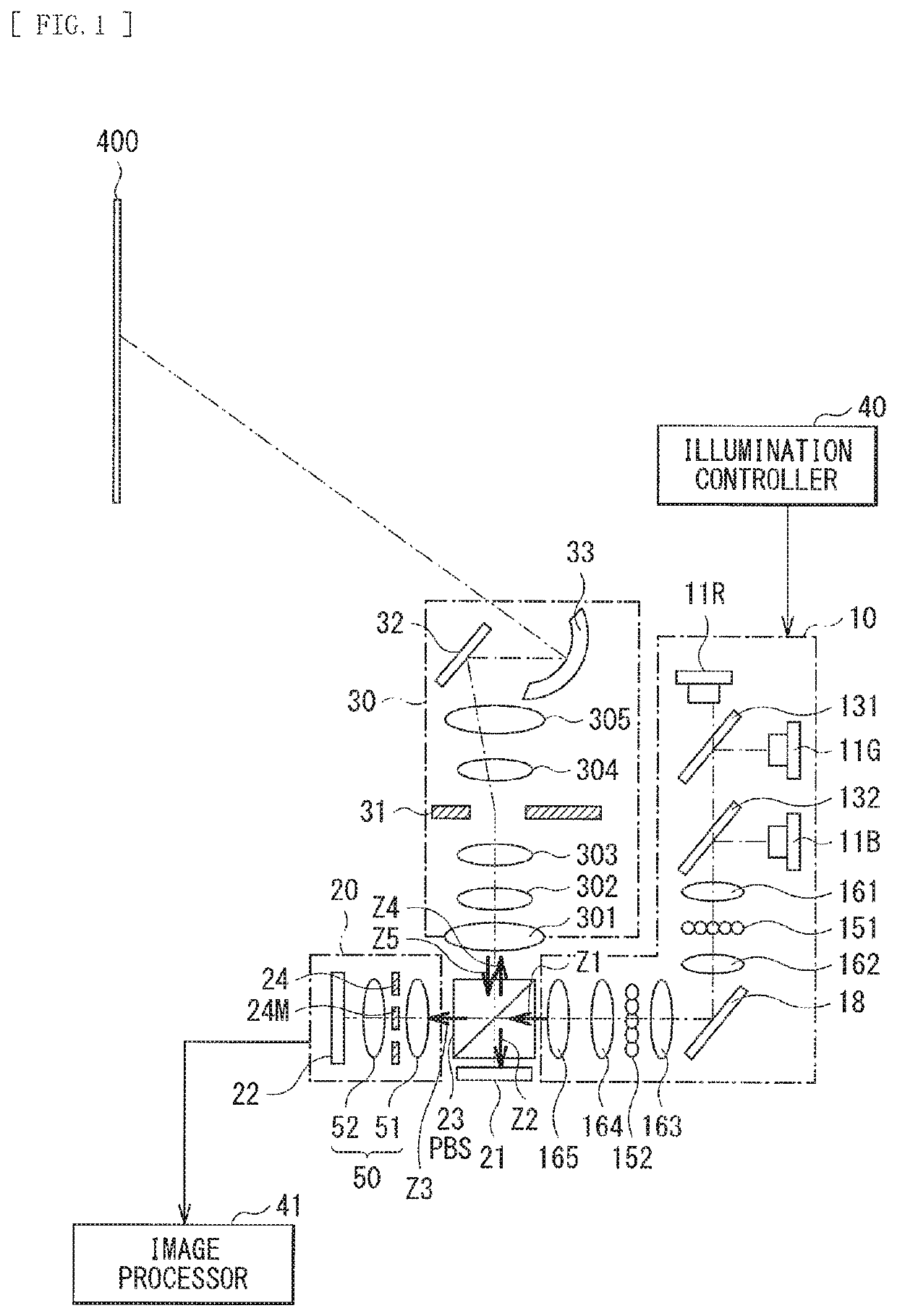
The projection display unit includes an illumination section including one or a plurality of light sources, a light valve that modulates light emitted from the illumination section and outputs the modulated light, a projection lens section that projects the light outputted from the light valve onto a projection surface, a light-receiving section including an imaging device that receives light incident via the projection lens section, and an optical device that allows for splitting into respective optical paths that pass through the illumination section, the light valve, and the light-receiving section. A first range corresponding to a portion of a pupil range of the projection lens section is assigned for projection, and the light-receiving section includes a light-shielding part that performs light-shielding of a selective part corresponding to the first range, at a position substantially optically conjugate with respect to an aperture of the projection lens section.
Description
CROSS REFERENCE TO RELATED APPLICATIONS[0001]This application is a U.S. National Phase of International Patent Application No.: PCT / JP2017 / 003583 filed on Feb. 1, 2017, which claims priority benefit of Japanese Patent Application No. JP 2016-082628 filed in the Japan Patent Office on Apr. 18, 2016. Each of the above-referenced applications is hereby incorporated herein by reference in its entirety.TECHNICAL FIELD[0002]The present disclosure relates to a projection display unit having an imaging function.BACKGROUND ART[0003]In recent years, there has been proposed a projection display unit that incorporates a light-receiving section in a projector module, and is able to read information in a projection surface (e.g., PTLs 1 and 2).CITATION LISTPatent Literature[0004]PTL 1: Japanese Unexamined Patent Application Publication No. 2003-44839[0005]PTL 2: Japanese Unexamined Patent Application Publication No. 2015-64550[0006]PTL 3: Japanese Unexamined Patent Application Publication No. 200...
Claims
Login to View More Application Information
Patent Timeline
 Patent Type & AuthorityPatents(United States)
IPC IPC(8): H04N5/225G06F3/0346G03B21/00G03B21/14H04N5/74G02B27/28H04N5/238H04N9/31G03B21/20H04N23/75
CPCH04N9/3197H04N9/3141G06F3/0346H04N5/2251G03B21/2013G03B21/14H04N5/2257H04N9/3155H04N5/74G03B21/00G03B21/2033G02B27/283H04N5/238H04N9/3176G03B21/208H04N9/3152G02B27/0961H04N9/315H04N23/57H04N23/50H04N23/75
InventorYASUI, TOSHIFUMI
OwnerSONY CORP