
Baseline shift determination for a photon detector

a detector and baseline technology, applied in tomography, x-ray spectral distribution measurement, instruments, etc., can solve the problem that the performance of photon counting detectors can be severely degraded at high x-ray flux

Active Publication Date: 2020-05-26
KONINKLJIJKE PHILIPS NV
View PDF42 Cites 2 Cited by
  • Summary
  • Abstract
  • Description
  • Claims
  • Application Information

AI Technical Summary

Benefits of technology

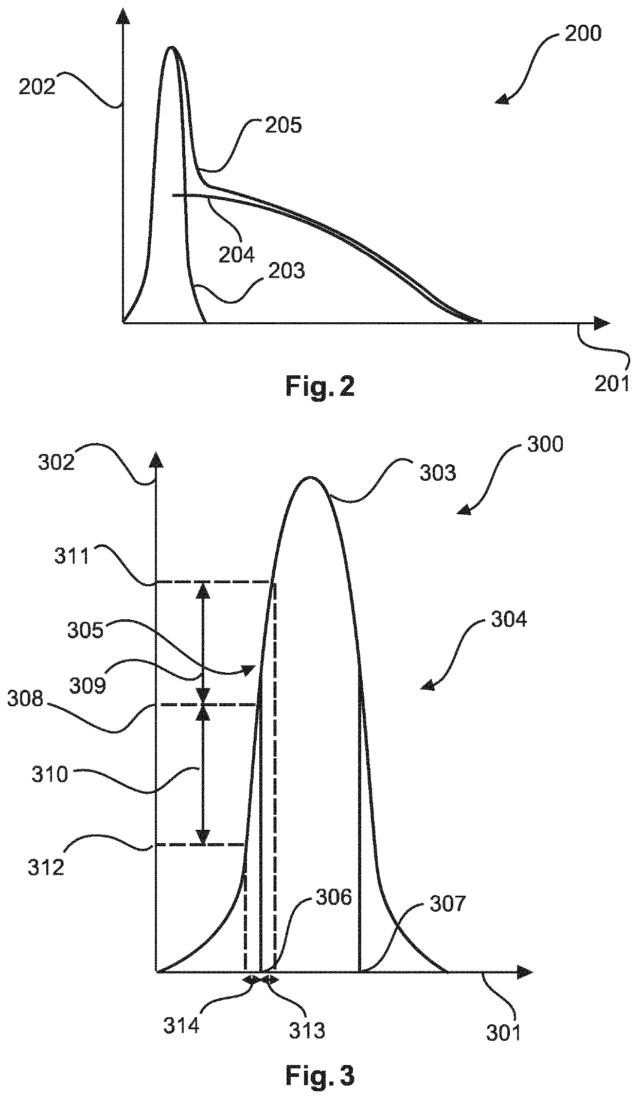
The patent text describes a method to improve the image quality of X-ray examination devices by measuring the pulse height of photons and correcting for changes in the DC component of the analog signal. By measuring two rates of exceeding pulse height thresholds and using two thresholds, the baseline shift can be determined more accurately. A storage unit can be used to correct the output of the processing unit with the stored baseline shift. The control unit can be a shutter or a grid switching device of the X-ray source to ensure that the change in the first rate is indicative of a true baseline shift unaffected by X-ray incidents at that very moment in time.

Problems solved by technology

Photon counting detector performance can be severely degraded at high X-ray flux due to uncontrollable and unpredictable changes in the baseline of the analogue signal of the photon counting detector and probed by the readout ASIC.

Method used


Image

  • Baseline shift determination for a photon detector
  • Baseline shift determination for a photon detector
  • Baseline shift determination for a photon detector

Examples


Embodiment Construction

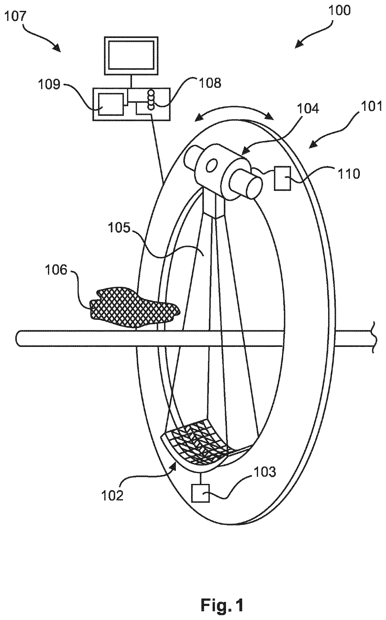
[0051]In FIG. 1, an X-ray examination device 100 according to an exemplary embodiment of the invention is shown. The X-ray examination device 100 comprises a gantry 101 which comprises an X-ray source 104 and a photon detector 102. The X-ray source 104 and the photon detector 102 can be rotated to different angular positions of the gantry 101 such that a probe 106 can be examined from different angles. The X-ray source 104 is configured to emit X-rays 105, which at least partly penetrate through the probe 106 and are detected by the photon detector 102. The photon detector 102 comprises a processing unit 103 for processing an electrical signal generated by the photon detector 102 of the X-ray examination device 100. The processing unit 103 is configured to determine a baseline shift of the electrical signal by determining a change of a first rate of exceeding a first pulse height threshold by the electrical signal. Furthermore, the first pulse height threshold is a pulse height at a...


PUM


Abstract

The present invention relates to determining baseline shift of an electrical signal generated by a photon detector (102) of an X-ray examination device (101). For this purpose, the photon detector comprises a processing unit (103) that is configured to determine a first crossing frequency of a first pulse height threshold by the electrical signal generated by the photon detector. The first pulse height threshold is located at a first edge of a noise peak in the pulse height spectrum of the electrical signal.

Description

CROSS REFERENCE TO RELATED APPLICATIONS[0001]This application is the U.S. National Phase application under 35 U.S.C. § 371 of International Application No. PCT / EP2015 / 079181, filed Dec. 10, 2015, published as WO 2016 / 096580 on Jun. 23, 2016, which claims the benefit of European Patent Application Number 14198239.7 filed Dec. 16, 2014. These applications are hereby incorporated by reference herein.FIELD OF THE INVENTION[0002]The present invention relates to the determination of the baseline shift of a photon detector. In particular, the present invention relates to a processing unit, a photon detector, an X-ray examination device, a method, a program element, and a computer-readable medium.BACKGROUND OF THE INVENTION[0003]Photon counting detector performance can be severely degraded at high X-ray flux due to uncontrollable and unpredictable changes in the baseline of the analogue signal of the photon counting detector and probed by the readout ASIC. These changes in the baseline can ...

Claims


Application Information

Patent Timeline
Patent Type & Authority Patents(United States)
IPC IPC(8): A61B6/03H05G1/30G01T7/00G01T1/40G01T1/24A61B6/00
CPCG01T1/24A61B6/032A61B6/4208A61B6/52A61B6/5205A61B6/482A61B6/4241A61B6/585A61B6/4233G01T7/005A61B6/42A61B6/582G01T1/40H05G1/30A61B6/58A61B6/586
Inventor ROESSL, EWALD
Owner KONINKLJIJKE PHILIPS NV
Learn More