Power delivery device for automatic transmission

a technology of automatic transmission and power delivery device, which is applied in the direction of fluid actuated clutches, non-mechanical actuated clutches, clutches, etc., can solve the problems of clutch operation efficiency deterioration, clutch damage, and inability to precisely control the operating speed and coupling force for each operating stage, etc., to achieve secure quick response and great coupling force

Active Publication Date: 2020-05-26
HYUNDAI MOTOR CO LTD +1
View PDF8 Cites 0 Cited by
  • Summary
  • Abstract
  • Description
  • Claims
  • Application Information

AI Technical Summary

Benefits of technology

[0010]Various aspects of the present invention are directed to providing a power delivery device configured for an automatic transmission having advantages of rapidly controlling a gap between friction members and securing quick responsiveness and great coupling force by applying dual pistons sequentially operated to operate a clutch.
[0031]According to an exemplary embodiment of the present invention, responsiveness may be improved by applying dual pistons for operating a clutch and rapidly controlling a gap between friction members with high speed, and power delivery efficiency may be increased by securing coupling force.
[0032]Since accumulated fatigue repeatedly applied to a clutch plate is minimized by rapidly controlling the gap between the friction members and achieving sufficient coupling force by use of the dual pistons, damage of the clutch may be prevented.
[0033]According to an exemplary embodiment of the present invention, drag loss when releasing the clutch is reduced by a return spring which is directly applied to the dual pistons and balance hydraulic pressure supplied between the dual pistons and a spring retainer. Furthermore, control reliability may be enhanced by countervailing remaining centrifugal hydraulic pressure by the balance hydraulic pressure.
[0034]Furthermore, since hydraulic pressure control is started at a region where hydraulic pressure is greater than a predetermined spring force of the return spring applied to the dual pistons, hydraulic pressure solenoid valve is not controlled at an unstable low-pressure region and control reliability may be enhanced.

Problems solved by technology

Recently, a clutch provides quick operating speed of a piston and great coupling force in this respect, but operating speed and coupling force are not precisely controlled for each operating stage.
Accordingly, operating efficiency of a clutch may be deteriorated.
Furthermore, as great coupling force of the piston is repeatedly applied to the clutch plate with quick operating speed, the clutch may be damaged due to accumulated fatigue.

Method used


Image

  • Power delivery device for automatic transmission
  • Power delivery device for automatic transmission
  • Power delivery device for automatic transmission

Examples


Embodiment Construction

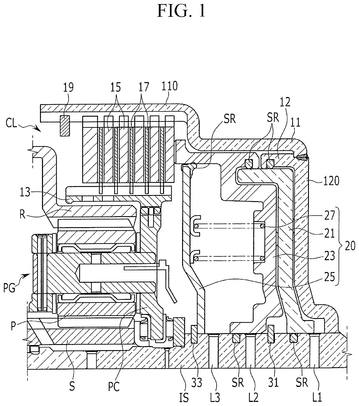
[0041]Reference will now be made in detail to various embodiments of the present invention(s), examples of which are illustrated in the accompanying drawings and described below. While the invention(s) will be described in conjunction with exemplary embodiments of the present invention, it will be understood that the present description is not intended to limit the invention(s) to those exemplary embodiments. On the other hand, the invention(s) is / are intended to cover not only the exemplary embodiments of the present invention, but also various alternatives, modifications, equivalents and other embodiments, which may be included within the spirit and scope of the invention as defined by the appended claims.

[0042]Hereinafter, an exemplary embodiment of the present invention will be described in detail with reference to the accompanying drawings.

[0043]However, parts which are not related with the description are omitted for clearly describing the exemplary embodiments of the present ...


PUM


Abstract

A power delivery device for an automatic transmission may include a clutch drum connected to an input shaft, a clutch disposed in the clutch drum and including a friction member connected to a planet carrier of a planetary gear set through a clutch hub, and a piston device disposed corresponding to the clutch and operating the clutch by hydraulic pressure.

Description

CROSS-REFERENCE TO RELATED APPLICATION[0001]The present application claims priority to Korean Patent Application No. 10-2017-0169259 filed on Dec. 11, 2017, the entire contents of which is incorporated herein for all purposes by this reference.BACKGROUND OF THE INVENTIONField of the Invention[0002]The present invention relates to a power delivery device for an automatic transmission. More particularly, the present invention relates to a power delivery device for an automatic transmission which controls a gap between friction members and provides coupling force optimized for each operating stage by use of dual pistons.Description of Related Art[0003]Environmentally-friendly technique of vehicles is very important technique on which survival of future motor industry is dependent. As regulations of exhaust gas become tightened, vehicle makers are focusing on development of environmentally-friendly vehicles to meet environment and fuel consumption regulations.[0004]To enhance of fuel ec...

Claims


Application Information

Patent Timeline
Patent Type & Authority Patents(United States)
IPC IPC(8): F16D25/0638F16D13/52F16H57/08
CPCF16H57/08F16D25/0638F16D13/52F16D2300/08F16H2057/087F16D25/086
Inventor SHIN, YONG UKPARK, JUHYEONCHAE, MINHOJI, SEONGWOOK
Owner HYUNDAI MOTOR CO LTD
Why Eureka
Try Eureka