
Medical cutting device comprising a rotating knife

a cutting device and rotating blade technology, applied in the field of medical cutting devices, can solve the problems of affecting the cutting process, affecting the cutting effect, so as to achieve convenient and safe cutting, uniform cutting results, and simple and cost-effective

Active Publication Date: 2020-05-26
HEINZ KURZ GMBH
View PDF4 Cites 1 Cited by
  • Summary
  • Abstract
  • Description
  • Claims
  • Application Information

AI Technical Summary

Benefits of technology

The present invention aims to improve a medical cutting device in a simple and cost-effective way, while maintaining its advantages and avoiding its disadvantages. Specifically, the invention aims to ensure that the cutting procedure is easy and safe, resulting in high-quality cut products. Furthermore, the invention offers the possibility of automated cutting.

Problems solved by technology

These shims, similar to the cutting device itself, must be thoroughly cleaned and kept sterile, and they must be handled separately in this manner before every operation, which is a time-consuming process that is susceptible to error.
This poses a great logistical challenge in terms of supplying sterilized materials.
Moreover, handling the shims is not entirely easy.
For example, due to the small size of the shims, it is not always possible to label them adequately and in an easily recognized manner, even though this is necessary in order to ensure that precisely the proper shim having the particular size that is required is available during the operation.
The disadvantage of this known cutting device, however, is that the production of parts is highly complex.
Products produced using injection-molding technology in particular have the characteristic that considerable problems can result when walls are very thin.
As a consequence thereof, the products generally cannot be produced cost-effectively, due to the financial outlay involved.
When this improved device is utilized, however, there is also a certain risk of injury for the person handling the device, because the cutting blade, before being inserted into the guide slot, is freely accessible and, therefore, can cut the user in the finger if a clumsy movement is carried out.
Yet another disadvantage of this known device (as well as of the above-discussed prior art) is that the knife for cutting off the desired cartilage slice must be handled using sawing or chopping motions, which often results in non-uniform cutting results.
In addition, the cutting procedure cannot be automated in any of the known devices, but rather absolutely must always be carried out manually.

Method used


Image

  • Medical cutting device comprising a rotating knife
  • Medical cutting device comprising a rotating knife
  • Medical cutting device comprising a rotating knife

Examples


Embodiment Construction

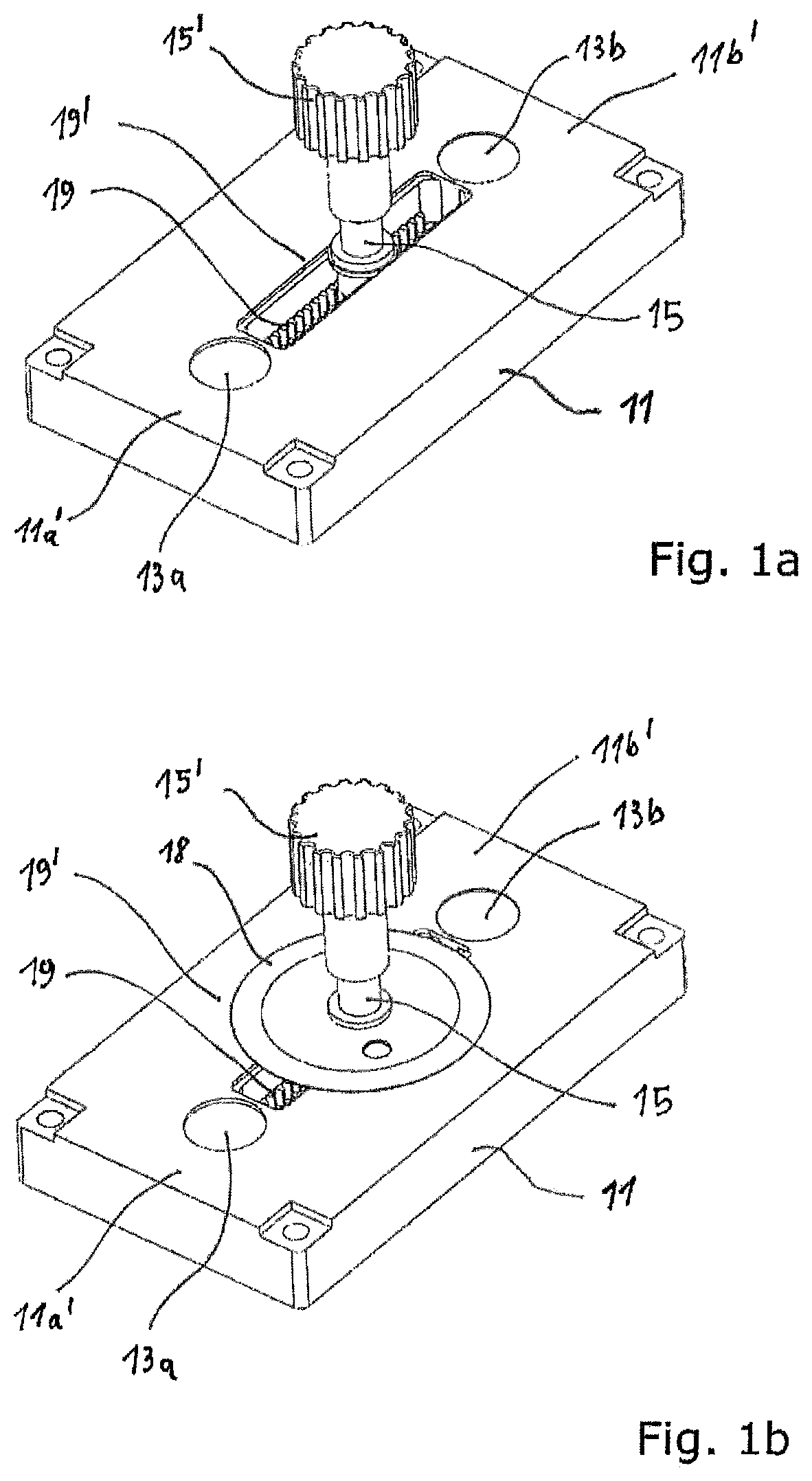
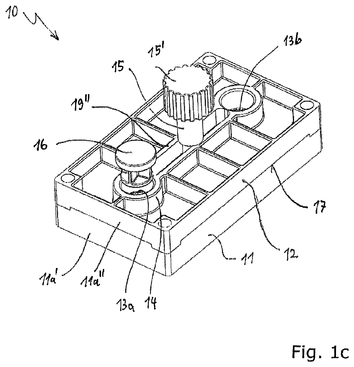
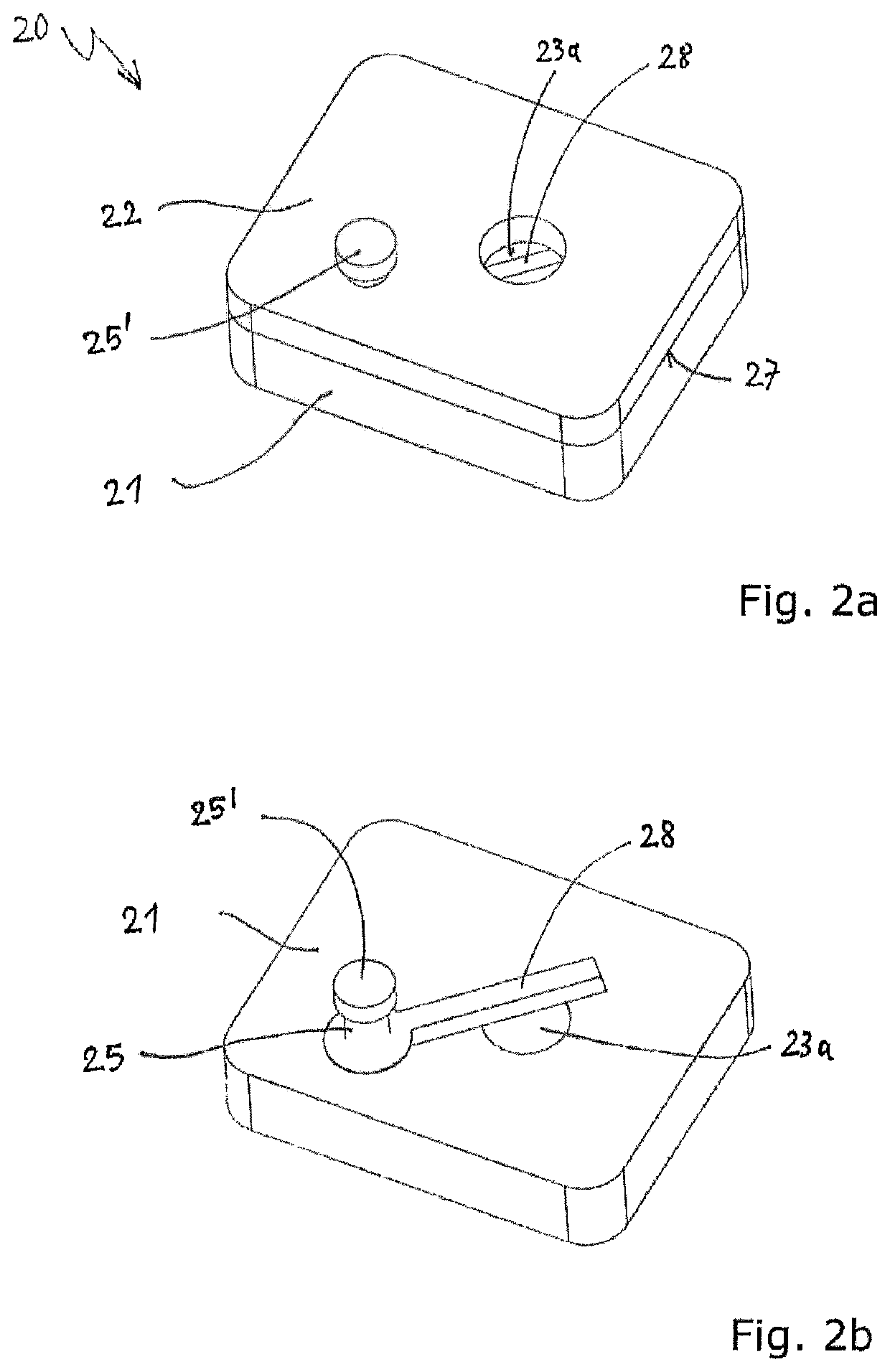
[0060]The embodiments of the medical cutting device 10; 20; 30; 40 according to the invention, which is depicted in a schematic, spatial manner in the figures of the drawing, are used for creating thin tissue or cartilage slices from a larger piece of cartilage, and are made of a serializable material, preferably a serializable plastic, in an injection molding process in particular, possibly also being made of metal. These embodiments comprise a device body 11; 21; 31; 41 and a cover 12; 22; 32; 42, wherein a first holding device is provided, which has a first working section 11a′ including a first recess 13a; 23a; 33a; 43a which disposed on the top side of the device body 11; 21 and is enclosed by a first limiting ridge 14 in entirety or, alternatively, in embodiments which are not represented in the drawing, only partially in each case by means of several individual ridges. The limiting ridge 14 can have a cross-section which is circular or oval or polygonal, in particular square,...


PUM

PropertyMeasurementUnit
pressureaaaaaaaaaa
distance daaaaaaaaaaa
thicknessaaaaaaaaaa

Abstract

A medical cutting device for creating thin slices, has a device body, a cover, a working section which rigidly adjoins a connecting section, and a recess on the top side, which is enclosed by a delimiting ridge. The cover comprises a counterpart to the connecting section adjoined by a pressure section which is positioned opposite the recess at a distance da, and therefore a guide slot extending between the working section and the pressure section remains free for a cutting blade. The distance of the guide slot to the bottom surface of the recess, which is defined by the distance da, defines the thickness, which can be achieved, of a slice to be created. The cutting blade is disposed within the guide slot and is rigidly connected to a rotatable shaft extending perpendicularly to the plane of the guide slot and extends through a recess in the cover.

Description

CROSS REFERENCE TO RELATED APPLICATIONS[0001]This application claims priority under 35 USC 119 of German Patent Application No. 10 2017 111 634.6 filed on May 29, 2017, the disclosure of which is herein incorporated by reference.BACKGROUND OF THE INVENTION[0002]The invention relates to a medical cutting device for creating thin tissue or cartilage slices, comprising a device body and a cover, wherein a first holding device is provided, which includes a first working section comprising a first recess which is located on the top side of the device body, the recess being entirely or partially enclosed by a first limiting ridge. The device body comprises a connecting section which is directly, rigidly adjoined by the first working section. The cover comprises a counterpart to the connecting section which is directly, rigidly adjoined by a first pressure section. In the operating state of the cutting device, the first pressure section is disposed opposite the first recess in the first wo...

Claims


Application Information

Patent Timeline
Patent Type & Authority Patents(United States)
IPC IPC(8): G01N1/00G01N1/06A61F2/46B26D1/143B26D3/28B26D7/02B26D1/26B26D5/08A61F2/30A61B17/16A61B17/00A61F11/00
CPCB26D7/02B26D1/143A61F2/4644B26D5/086G01N1/06B26D1/26B26D5/08B26D3/28A61F2/30756A61B17/1635G01N2001/065A61B17/1688G01N2001/061A61B17/1679A61B2017/00787A61F2002/3096A61B2017/00969A61B2017/00792A61F11/004A61F11/20
Inventor GAECKLE, MARKUSLANG, AXEL
Owner HEINZ KURZ GMBH
Learn More