Software defined battery charger system and method

a technology of software defined batteries and chargers, applied in emergency power supply arrangements, instruments, transportation and packaging, etc., can solve the problems that building management systems often cannot rely on the power grid as a sole source of input power, and achieve the effects of reducing life, maximizing battery life, and reducing cos

Active Publication Date: 2020-05-26
JOHNSON CONTROLS TYCO IP HLDG LLP
View PDF2 Cites 0 Cited by
  • Summary
  • Abstract
  • Description
  • Claims
  • Application Information

AI Technical Summary

Benefits of technology

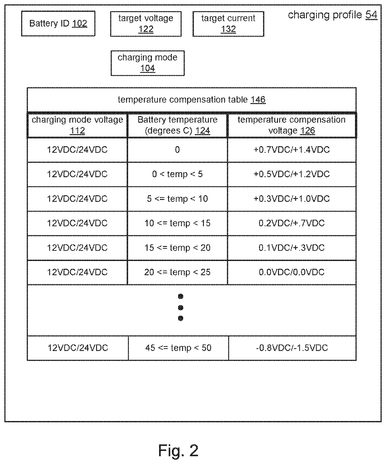
[0009]The charging systems typically provide the following base set of features. The charging systems provide both a float charge and a fast charge output voltage with temperature compensation, limit charging current proportional to battery size, support different battery chemistries, and limit charging voltage based on battery chemistry. The charging systems must also operate in a way that maximizes the life of the batteries. A set of operating parameters for configuring the power converter is built from these features.
[0012]Maximizing a battery's life requires a charging system that adjusts its output voltage applied to the batteries. The charging system typically adjusts the output voltage based on the state-of-charge (percent charged) as well as temperature. When a battery is depleted and being recharged it will accept charge at a faster rate if the charging voltage is increased. This increased voltage can only be applied for a short time otherwise damage and reduced life would result. As a result chargers can be designed to have a ‘fast’ charging voltage during recharge and a lower ‘float’ voltage for extended shelf-life.
[0013]However, designing charging systems to provide the base set of features is complex and costly, prompting manufacturers to make design compromises to reduce complexity and / or cost. In one example, rather than setting the output current that is appropriate for each battery size, some charging systems provide only two output current levels, appropriate for “small” and “large” sizes of batteries. In another example, some charging systems use a single output voltage for both the fast charging and float charging modes. This can increase recharge cycle times and / or reduce battery life. Some charging systems require an operator to manually configure the output voltage for each battery chemistry, or support only one type of battery chemistry. Yet other systems make compromises with regards to temperature compensation, such as compensating for temperature only during fast charging mode or not compensating for temperature at all.
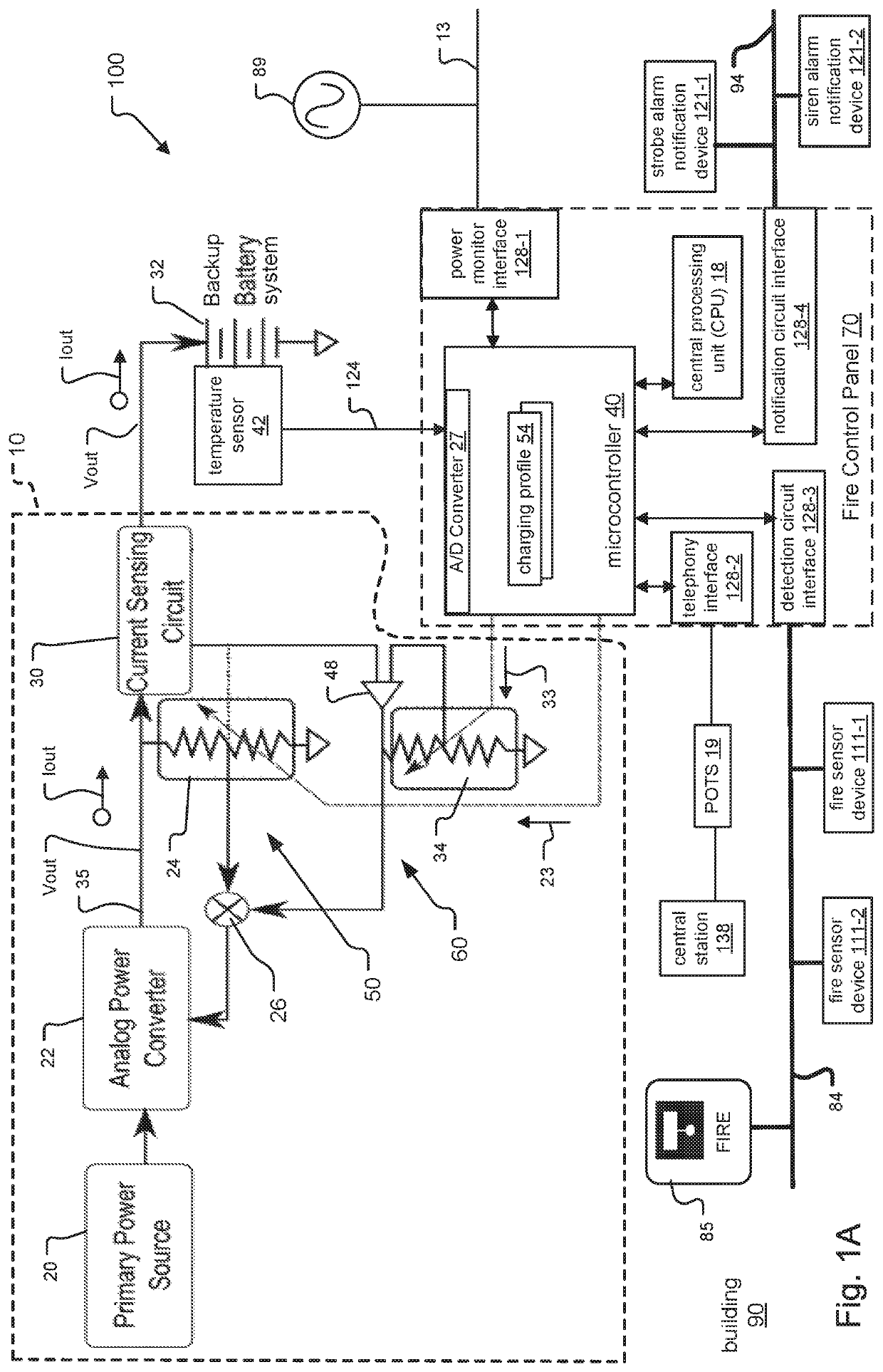
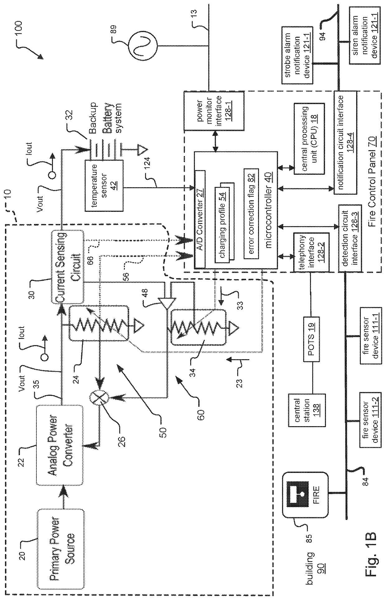
[0015]An inventive building management system that includes a charging system is proposed, where a system panel for controlling the building management system also controls the charging system. Specifically, the charging system is under control of at least one microcontroller of the system panel. The microcontroller of the system panel (“microcontroller”) provides the functionality of the dedicated controller in traditional charging systems, in one example. As a result, the dedicated controller of the traditional charging system is no longer needed, which reduces charging system complexity and manufacturing cost.

Problems solved by technology

These building management systems often cannot rely upon the power grid as a sole source of input power.

Method used


Image

  • Software defined battery charger system and method
  • Software defined battery charger system and method
  • Software defined battery charger system and method

Examples


Embodiment Construction

[0038]The invention now will be described more fully hereinafter with reference to the accompanying drawings, in which illustrative embodiments of the invention are shown. This invention may, however, be embodied in many different forms and should not be construed as limited to the embodiments set forth herein; rather, these embodiments are provided so that this disclosure will be thorough and complete, and will fully convey the scope of the invention to those skilled in the art.

[0039]As used herein, the term “and / or” includes any and all combinations of one or more of the associated listed items. Further, the singular forms of the articles “a”, “an” and “the” are intended to include the plural forms as well, unless expressly stated otherwise. It will be further understood that the terms: includes, comprises, including and / or comprising, when used in this specification, specify the presence of stated features, integers, steps, operations, elements, and / or components, but do not prec...


PUM


Abstract

A backup battery charging system for a building management system is disclosed. Components of the charging system include an analog power converter, a voltage feedback loop and a current feedback loop. The feedback loops each include at least one digital resistor. The system panel, in turn, includes at least one microcontroller that controls the building management system and also controls the charging system. The charging system is “software defined,” in that the microcontroller controls the charging system by updating the digital resistors in the feedback loops to control the analog power converter. In one example, the building management system is a fire alarm system controlled by a fire control panel as the system panel.

Description

BACKGROUND OF THE INVENTION[0001]Building management systems such as building automation systems, fire alarm systems and intrusion detection systems are often installed within premises such as in a commercial, residential, or government building. Examples of these buildings include offices, hospitals, warehouses, public infrastructure buildings including subways and bus terminals, multi unit dwellings, schools or universities, shopping malls, government offices, and casinos, to list a few examples.[0002]Fire alarm systems typically include fire control panels that function as system controllers. Fire detection / signaling devices and alarm notification devices are then installed throughout the buildings and connected to the panels. Some examples of fire detection / signaling devices include smoke detectors, carbon monoxide detectors, flame detectors, temperature sensors, and / or pull stations (also known as manual call points). Some examples of fire notification devices include speakers,...

Claims


Application Information

Patent Timeline
Patent Type & Authority Patents(United States)
IPC IPC(8): H02J7/00H02J9/04H02J9/06H02J7/02G01R22/00
CPCH02J9/04H02J9/061H02J7/0071H02J7/00H02J7/02G01R22/00H02J2207/20H02J7/04
Inventor CIANFROCCO, DANIEL P.GOUIN, ALEXANDRE
Owner JOHNSON CONTROLS TYCO IP HLDG LLP
Why Eureka
Try Eureka