Stationary induction apparatus core

a technology of induction apparatus and core, which is applied in the direction of transformer/inductance details, electrical apparatus, transformer/inductance magnetic core, etc., can solve the problems of increasing the stray loss, unable to obtain sufficient rigidity, and unable to achieve sufficient mechanical strength and rigidity, etc., to achieve the effect of improving mechanical strength and low magnetic loss

Active Publication Date: 2020-05-26
HITACHI LTD
View PDF28 Cites 0 Cited by
  • Summary
  • Abstract
  • Description
  • Claims
  • Application Information

AI Technical Summary

Benefits of technology

[0009]The present, invention has been achieved in the light of the above respects. An object of the present invention is to provide a stationary induction apparatus core capable of improving a mechanical strength and ensuring a low magnetic loss without using a supporting member even when amorphous ribbons are used for an inner core.
[0011]According to the present embodiment, it is possible to obtain a stationary induction apparatus core capable of improving a mechanical strength and ensuring a low magnetic loss without using a supporting member even when amorphous ribbons are used for an inner core.

Problems solved by technology

However, the amorphous ribbons forming the core have properties of being hard and brittle, and hundreds of ribbons at a thickness of 25 μm are stacked for forming the core.
Owing to this, a sufficient mechanical strength and sufficient rigidity cannot be obtained.
Thus, unlike silicon steel sheets, the amorphous ribbons are difficult to self-stand.
However, when the amorphous ribbons are used for the inner core, a supporting member (for example, an SUS material) is necessary because of difficulty in malting the amorphous ribbons self-standing and this supporting member possibly, disadvantageously causes an increase in a stray loss.
Furthermore, since a load of the silicon steel sheets is applied to the amorphous ribbons, the load possibly, disadvantageously causes an increase in the magnetic loss.

Method used


Image

  • Stationary induction apparatus core
  • Stationary induction apparatus core
  • Stationary induction apparatus core

Examples


first embodiment

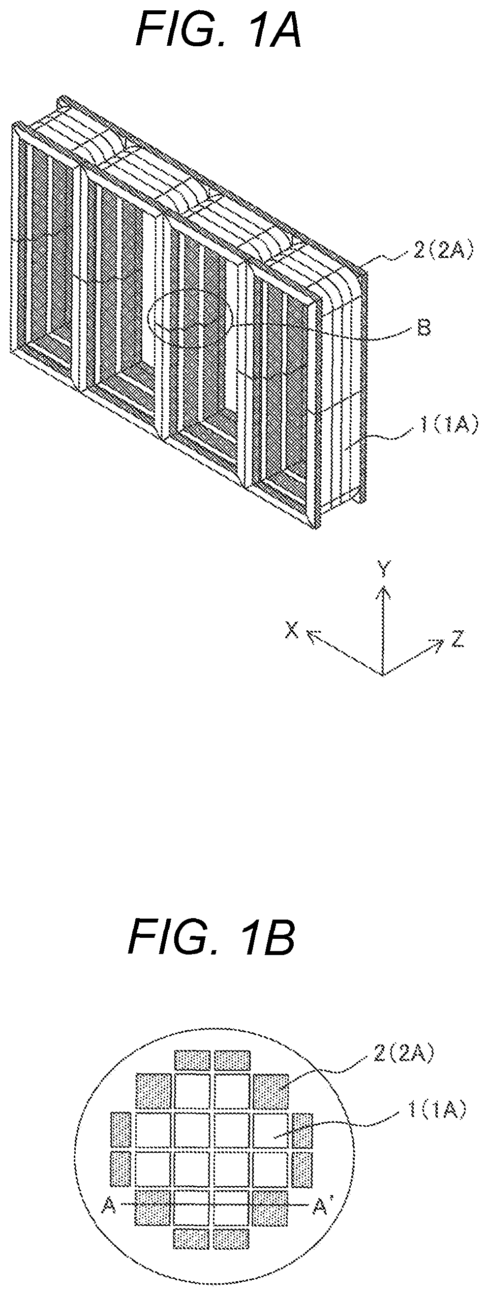
[0024]FIGS. 1A and 1B show a first embodiment of the stationary induction apparatus core according to the present invention. FIG. 1A shows the core viewed obliquely, and FIG. 1B is a detailed cross-sectional view of a part B of FIG. 1A in which a cross-section of a magnetic leg is partially enlarged to make an internal configuration of the magnetic leg clear.

[0025]For the stationary induction apparatus core in the present embodiment, it is defined in FIG. 1A that an arrow X direction is a lateral direction, an arrow Y direction is a longitudinal direction, and an arrow Z direction is a width direction.

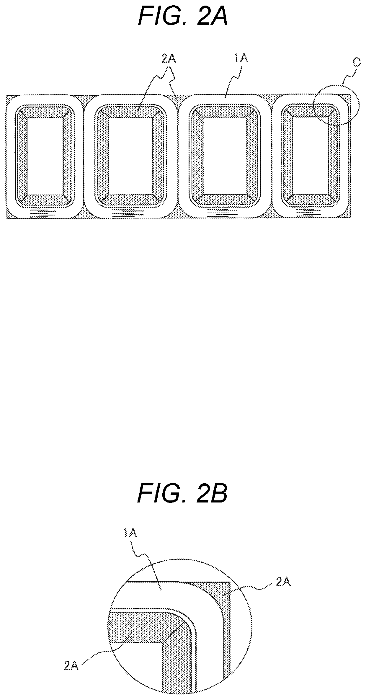
[0026]As shown in FIGS. 1A and 1B, the stationary induction apparatus core in the present embodiment is generally configured with inner cores 1 formed from amorphous ribbons and outer cores 2 formed from silicon steel sheets, the outer cores 2 being disposed on two sides of each inner core 1 in a depth direction (width direction: the arrow Z direction of FIG. 1A) as opposed to a standi...

second embodiment

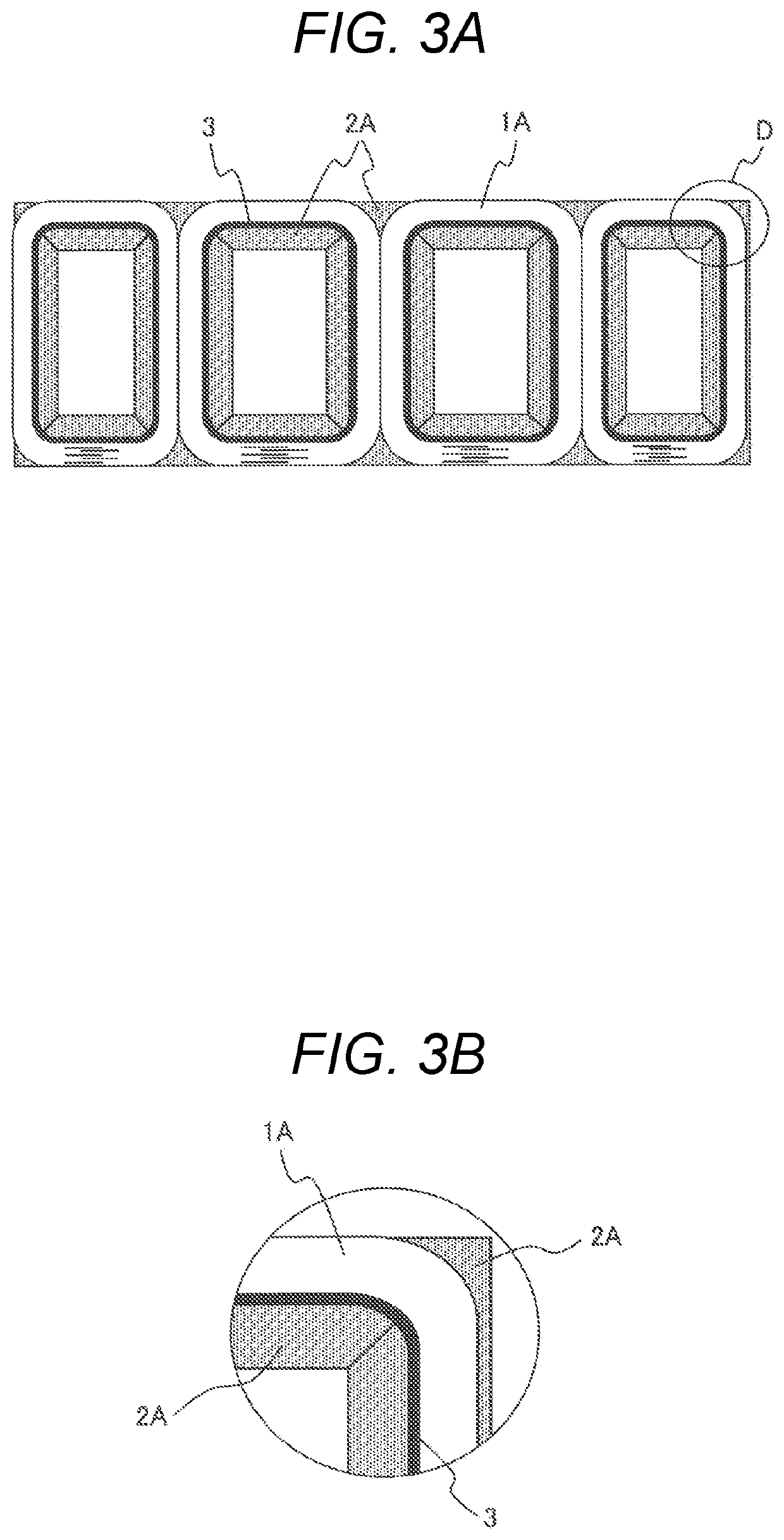
[0036]FIGS. 3A and 3B show a second embodiment of the stationary induction apparatus core according to the present invention.

[0037]The stationary induction apparatus core in the present embodiment shown in FIGS. 3A and 3B is configured, in addition to a configuration described in the above first embodiment, such that a silicon steel sheet 3 wound into a generally rectangular shape is disposed between an outermost periphery of each stacked core 2A formed from the silicon steel sheets and an innermost periphery of each wound core 1A formed from the amorphous ribbons.

[0038]With such a configuration of the present embodiment, it is possible not only to attain similar effects to those of the first embodiment, but also to protect the amorphous ribbons of the wound cores 1A from breakage due to contact with the stacked cores 2 by disposing the silicon steel sheet 3.

third embodiment

[0039]FIGS. 4A and 4B show a third embodiment of the stationary induction apparatus core according to the present invention.

[0040]The stationary induction apparatus core in the present embodiment shown in FIGS. 4A and 4B is configured, in addition to the configuration described in the above first embodiment, such that a gap 4a formed between silicon steel sheets 2a and 2b in a step-lap joint section 4 formed in each corner portion of the stacked core 2A formed from the silicon steel sheets is made large to have a gap length at which a magnetic resistance of the wound cores 1A is equal to that of the stacked cores 2A.

[0041]With such a configuration of the present embodiment, it is possible not only to attain the similar effects to those of the first embodiment, but also to make the magnetic resistance of the wound cores 1A formed from the amorphous ribbons generally equal to that of the stacked cores 2A formed from the silicon steel sheets and to reduce a deviation of flux densities ...


PUM

PropertyMeasurementUnit
thicknessaaaaaaaaaa
magnetic flux densityaaaaaaaaaa
saturation flux densityaaaaaaaaaa

Abstract

An object of the present invention is to improve a mechanical strength and to ensure a low magnetic loss without using a supporting member even when amorphous ribbons are used for an inner core. To attain the object, a stationary induction apparatus core of the present invention includes an inner core formed from the amorphous ribbons and outer cores formed from silicon steel sheets, the outer cores being disposed on two sides of the inner core in a depth direction as opposed to a standing direction of the inner core in such a manner as to sandwich the inner core therebetween.

Description

CLAIM OF PRIORITY[0001]The present application claims priority from Japanese Patent, application serial No. 2017-7353, filed on Jan. 19, 2017, the content of which is hereby incorporated by reference into this application.BACKGROUND OF THE INVENTION1. Field of the Invention[0002]The present invention relates to a stationary induction apparatus core, and particularly relates to a stationary induction apparatus core suited as a core that uses amorphous ribbons and silicon steel sheets for a stationary induction apparatus such as a transformer or a reactor.2. Description of the Related Art[0003]In recent years, for one type of stationary induction apparatus core that is, for example, an energy saving transformer core, an amorphous magnetic material with a low magnetic loss and excellent magnetic properties has been used. Amorphous ribbons used in the transformer core are produced by rapidly quenching a magnetic alloy melt, so that the amorphous ribbons are quite low in magnetic loss an...

Claims


Application Information

Patent Timeline
Patent Type & Authority Patents(United States)
IPC IPC(8): H01F27/24H01F3/10H01F3/04H01F3/02H01F27/26H01F27/245H01F27/25H01F27/34H01F3/14H01F41/02
CPCH01F3/10H01F27/263H01F27/245H01F3/02H01F27/25H01F27/34H01F3/14H01F27/2455H01F3/04H01F2003/106H01F41/0233H01F41/0226
Inventor KOBAYASHI, CHIEKURITA, NAOYUKIYAMAGISHI, AKIRA
Owner HITACHI LTD
Why Eureka
Try Eureka