Electroflotation apparatus having an outlet pipe with a low turbulence orifice

a technology of electro-flotation apparatus and outlet pipe, which is applied in the direction of flotation, solid separation, water/sludge/sewage treatment, etc., can solve the problems of affecting the aggregation of flocks from treated water, requiring relatively complex engineering designs, and requiring longer time to achieve aggregation of flocks. , to achieve the effect of increasing the aggregation of flocks

Active Publication Date: 2020-06-02
AXOLOT SOLUTIONS HLDG AB
View PDF11 Cites 3 Cited by
  • Summary
  • Abstract
  • Description
  • Claims
  • Application Information

AI Technical Summary

Benefits of technology

[0015]in order that the outlet pipe reduces the turbulence of the treated water from the electrolytic cell before the treated water is passed to the separation area such that aggregation of the flock in the separation area is increased. The design of the outlet pipe is specifically made to reduce flow rate, to reduce turbulence of the treated water in the outlet pipe, and especially to reduce the turbulence of the treated water in being released into the separation area.
[0028]Other embodiments relate to the separation area being a pool or a basin located to one side of the outlet pipe or the electrolytic cell. In these embodiments the pool or basin may be further located above the level of the outlet pipe or electrolytic cell. A pipe such as a curved pipe extends between the outlet pipe and the pool or basin for passing the treated water and flock from the outlet pipe to the pool or basin. In some embodiments, the apparatus comprises a linear stabilizing zone between the curved pipe and the pool or the basin. The linear stabilizing zone serves to stabilize aggregates to preserve them upon release into the pool or the basin and to increase aggregation of the flock in the separation area. In some embodiments, the apparatus comprises a conical outlet between the curved pipe and the pool or the basin. Also a conical outlet between the curved pipe and the pool or the basin may contribute to stabilizing aggregates to preserve them upon release into the pool or the basin and to increase aggregation of the flock in the separation area.

Problems solved by technology

However, a problem with the apparatuses disclosed by WO 2011 / 023851 and WO 2011 / 018556 is that the flock aggregate is readily broken up by the turbulent water flow exiting the electrolytic cell thereby hampering separation of the flock from the treated water.
The apparatuses of WO 96 / 15989 and WO 03 / 062152 require relatively complex engineering designs and a longer time is required to achieve separation of the flock from the treated water.
This increases operation costs.

Method used


Image

  • Electroflotation apparatus having an outlet pipe with a low turbulence orifice
  • Electroflotation apparatus having an outlet pipe with a low turbulence orifice
  • Electroflotation apparatus having an outlet pipe with a low turbulence orifice

Examples


Embodiment Construction

[0046]The following description focuses on embodiments of the present invention applicable to an electroflotation apparatus. However, it will be appreciated that the invention is not limited to these applications but may be applied to other separation processes which involve generation of a solid and subsequent separation of the solid from a liquid.

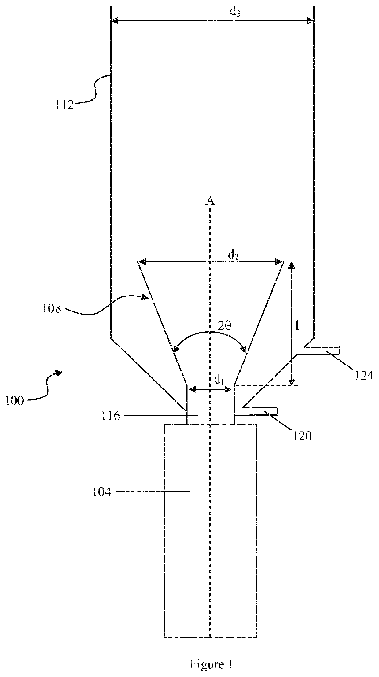
[0047]FIG. 1 illustrates an electroflotation apparatus 100. The apparatus broadly comprises an electrolytic cell 104, an outlet pipe 108, and a separation area in the form of a cylindrical tube 112. The outlet pipe 108 is connected to the electrolytic cell 104 and serves to pass the flock and treated water from the electrolytic cell 104 in a vertical direction to the separation area 112. A first end of the outlet pipe 108 has a cylindrical portion 116 that is connected to the top of the electrolytic cell 104. The flock and treated water enter the first end of the outlet pipe 108 and pass through the pipe before exiting a second end of the...


PUM

PropertyMeasurementUnit
thicknessaaaaaaaaaa
diameteraaaaaaaaaa
diameteraaaaaaaaaa

Abstract

An electroflotation apparatus for removing impurities from waste water includes an electrolytic cell for treating the waste water and generating a flock containing the impurities and an outlet pipe having a linear central axis located co-axially with the electrolytic cell for passing the water and flock from the electrolytic cell to a separation area. The outlet pipe comprises a first end connected to the electrolytic cell and having a first diameter, and a second end through which the treated water and flock exit the outlet pipe, the second end having a second diameter. The outlet pipe reduces the turbulence of the treated water from the electrolytic cell before the treated water is passed to the separation area such that aggregation of the flock in the separation area is increased.

Description

[0001]This application is a national phase of International Application No. PCT / EP2016 / 074055 filed Oct. 7, 2016, and claims priority to Swedish Application No. SE 1551302-1 filed on Oct. 8, 2015, which is incorporated herein by reference.FIELD OF THE INVENTION[0002]The present invention relates to an electroflotation apparatus for removing impurities from waste water. More particularly, the invention relates to an electroflotation apparatus comprising an outlet pipe with a low turbulence orifice.BACKGROUND[0003]The treatment of waste water and sewage by electroflotation to remove impurities is well known in the art. Such treatment of waste water generally involves an initial electrocoagulation step in which the waster water is fed into an electrolytic cell where electrical impulses are applied to the water to generate a flock containing the impurities. A flotation step follows in which the flock rises to the surface of the water where it can be removed by mechanical methods externa...

Claims


Application Information

Patent Timeline
Patent Type & Authority Patents(United States)
IPC IPC(8): C02F1/463C02F1/461C02F1/46C02F1/465B03D1/14
CPCC02F1/463C02F1/46114B03D1/1456B03D1/1437C02F1/465C02F2301/022C02F2201/4611C02F2201/003
Inventor GIAEVER, STIGHOLM, DANIEL
Owner AXOLOT SOLUTIONS HLDG AB
Why Eureka
Try Eureka