

Flight control device and flight control method for unmanned aerial vehicle
a flight control device and drone technology, applied in vehicle position/course/altitude control, process and machine control, instruments, etc., can solve the problems of drones that drones that cannot maintain the correct position, drones that cannot achieve autonomous flight in environments where drones cannot receive gps radio waves, etc., to achieve the effect of reducing measurement accuracy and low measurement accuracy
- Summary
- Abstract
- Description
- Claims
- Application Information
AI Technical Summary
Benefits of technology
Problems solved by technology
Method used
Image


Examples
first embodiment
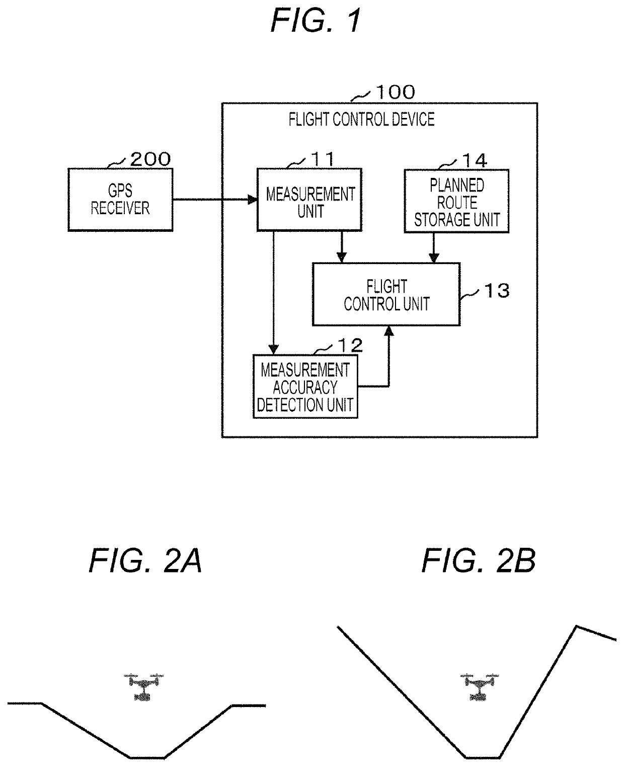
[0021]A first embodiment of the present invention will hereinafter be described with reference to drawings. FIG. 1 is a diagram illustrating an example of a functional structure of a flight control device according to the first embodiment. A flight control device 100 according to the first embodiment is mounted on an unmanned aerial vehicle (drone), and based on the position and the altitude measured using a GPS receiver 200, the flight control device 100 autonomously controls the flight of the drone in accordance with a planned route.
[0022]As illustrated in FIG. 1, the flight control device 100 according to the first embodiment includes a measurement unit 11, a measurement accuracy detection unit 12, and a flight control unit 13 as a functional structure thereof. In addition, the flight control device 100 includes a planned route storage unit 14 as a storage medium.
[0023]Each of the function blocks 11 to 13 can be configured by any of hardware, a digital signal processor (DSP), and...
second embodiment
[0047]Next, a second embodiment of the present invention will hereinafter be described with reference to drawings. The functional structure of the flight control device 100 according to the second embodiment is similar to that in FIG. 1. In addition, the second embodiment is similar to the first embodiment in that when the GPS measurement accuracy has decreased to be less than the predetermined value, the drone is caused to fly along the route different from the planned route and is returned to the different place on the planned route. The second embodiment is different from the first embodiment in the different route. The different route in the second embodiment includes four stages of a backward flight stage, an ascent flight stage, a maintaining flight stage, and a descent flight stage.
[0048]FIG. 5 is a diagram for describing the different route according to the second embodiment. In a manner similar to FIG. 3, FIG. 5 expresses the positions and the altitudes of the ten successiv...
third embodiment
[0055]Next, a third embodiment of the present invention will be described with reference to drawings. FIG. 6 is a diagram illustrating an example of a functional structure of a flight control device 100′ according to the third embodiment. In FIG. 6, a component denoted by the reference symbol shown in FIG. 1 has the same function and the description of such a component is omitted.
[0056]As illustrated in FIG. 6, in the third embodiment, a magnetic sensor 201 and an atmospheric pressure sensor 202 are provided in addition to the GPS receiver 200. The flight control device 100′ includes a measurement unit 11′, a measurement accuracy detection unit 12′, and a flight control unit 13′ instead of the measurement unit 11, the measurement accuracy detection unit 12, and the flight control unit 13 illustrated in FIG. 1.
[0057]In the third embodiment, the measurement unit 11′ measures the position, the direction, and the altitude of the drone by using the GPS receiver 200, the magnetic sensor 2...
PUM
 Abstract
Description
Claims
Application Information