Replaceable wheel or foot assembly and leg system for a sign display stand

a technology of display stands and wheels, applied in the field of display stands, can solve the problems of standing b>10/b> to potential damage, damage to the leg portion, damage to the floor, etc., and achieve the effects of reducing production costs, facilitating transportation, and facilitating the change of sign panels

Active Publication Date: 2020-06-02
STRUHL CLIFFORD
View PDF23 Cites 2 Cited by
  • Summary
  • Abstract
  • Description
  • Claims
  • Application Information

AI Technical Summary

Benefits of technology

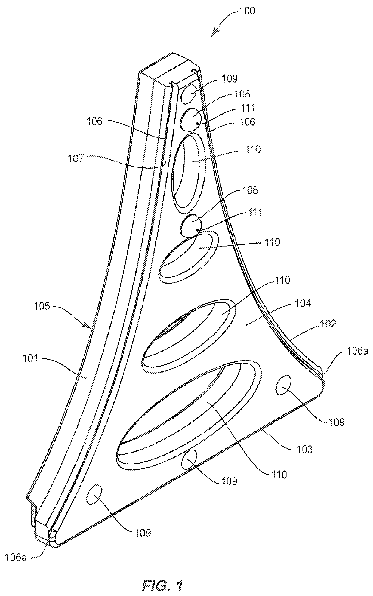
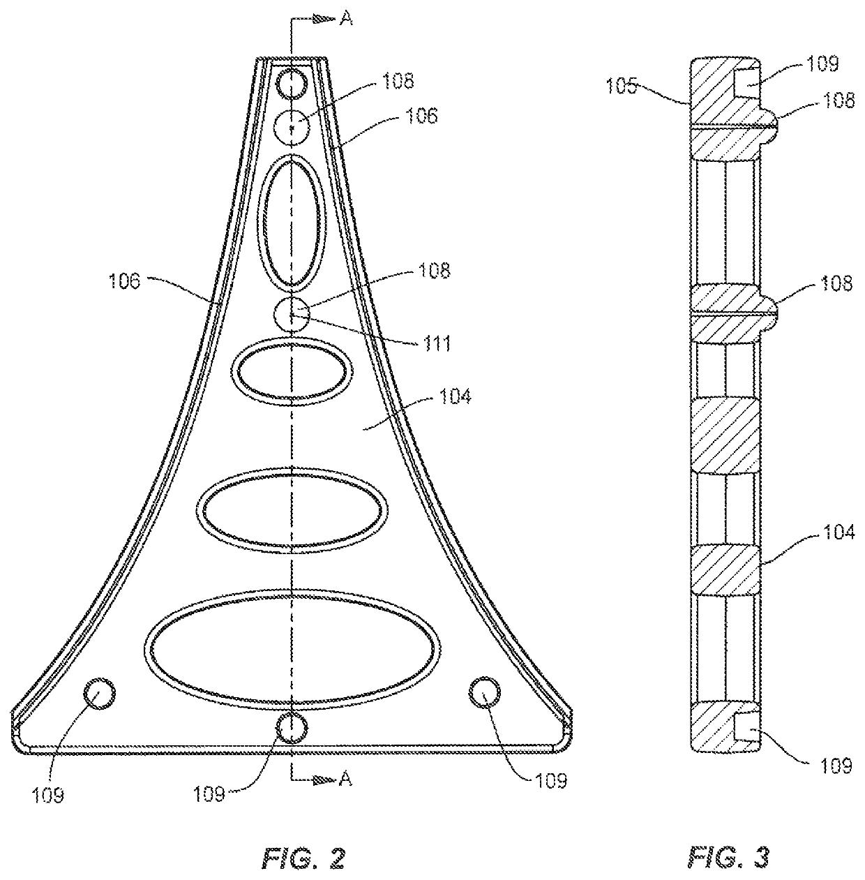
[0010]In one embodiment of the invention, the wheel assembly can include a cradle and structures and configurations adapted to attach the cradle to a leg portion of the display sign stand (or other object). In one embodiment of the invention, the wheel assembly can be clipped onto the stand or other object, without the need for screws, bolts or other fasteners. The wheel assembly can be attached by one or more of: a resilient clamping action, the interaction of protrusions, such as hooks or claws into recesses or grooves, screws or bolts, and / or with a tongue and groove arrangement. The wheel assembly attachment configuration can permit easy assembly and removal of the cradle from the leg of a display stand, or object. Furthermore, the assembly can be removed, the wheel removed and the wheel-less assembly replaced, to act as a protective foot to reduce wear on the bottom portion of the leg. This is particularly important with water filled designs.
[0011]In one embodiment of the invention, the wheel is located in the cradle, and positioned so that it will not contact the ground when the display stand is positioned in its normal assembled configuration, which may be inclined to the ground or other surface on which the stand is supported. The wheels can be positioned so that they extend substantially sideways from the frame and substantially above the ground, so that as the frame is tilted towards the wheels, the wheels will eventually become loaded with the weight of the display stand, the display stand will be lifted off the ground and the display stand can be moved, easily, because the wheels can roll freely in the tilted position.
[0012]The wheel assembly can be constructed with two flattened bottom portions, with the wheel extending from a side thereof. The first flattened bottom portion is preferably substantially perpendicular to the longitudinal axis of the leg, configured to rest flat when the leg is perpendicular to the ground. Therefore, if installed on an A-frame stand, the stand can rest on the first flat portion when the stand is in the collapsed travel configuration. The second flat bottom portion is preferably at an obtuse angle to the first flat portion and an acute angle to the longitudinal axis of the leg. The second flat portion can be located farther from the exposed portion of the wheel than the first flat portion, to rest flat on the ground when the leg is inclined to the ground, in an in-use A-frame position. Both positions protect the bottom of the leg from the ground, even if the wheel is not present. To that end, ribs, feet and other structures can be included at the bottom of the wheel, assembly to reduce problems associated with wear.
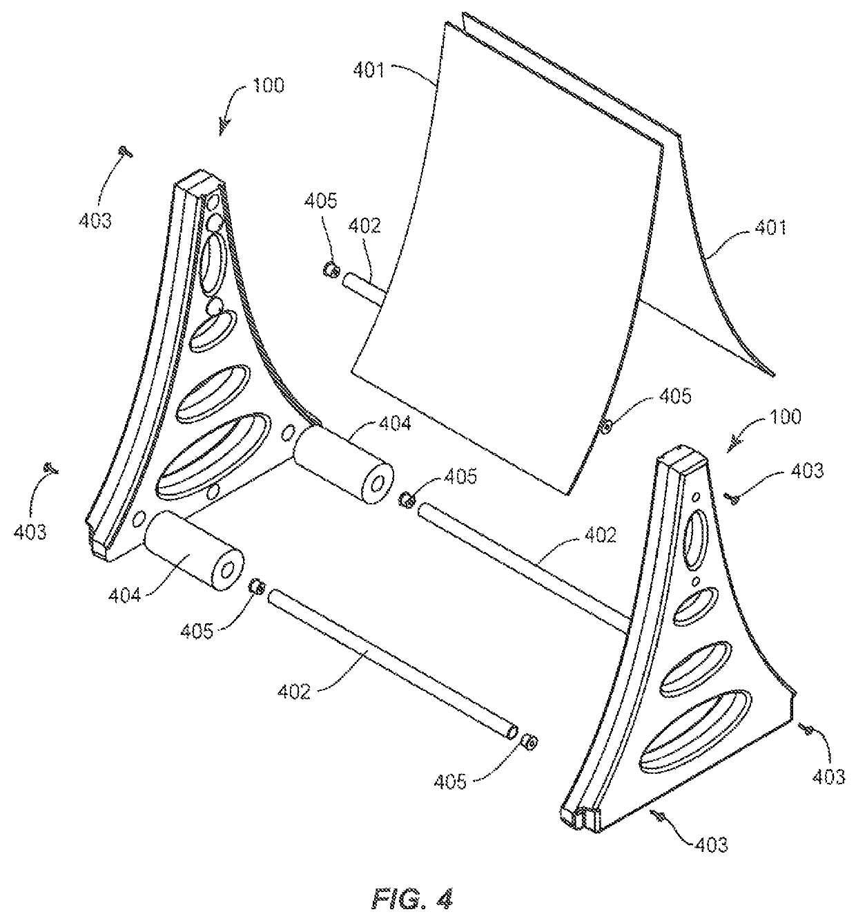
[0015]The stand itself can include a universal multi-use, interchangeable leg that allows the user to change sign panel size, height, format and display method quickly and easily without replacing the legs, which can be the most expensive part of the display stand. The stand can also be in the form with an A-frame design, which can be collapsed into a narrow profile for ease in transport.
[0016]A universal leg can provide the user with a variety of display options. From a manufacturing perspective, the universal leg is less expensive to produce, due to economies of scale and lower cost molding methods, and requires less inventory since one leg can replace many different leg styles.

Problems solved by technology

In order to move stand 10, all of stand 10 must be lifted and carried, which is undesirable and exposes stand 10 to potential damage.
Stand 10 can also be dragged on one or more of its legs, which it is also undesirable and can cause damage to the portion of the legs in contact with the ground and / or causes damage to the floor across which stand 10 is dragged.
Therefore, if the portions of the stand in contact with the ground become worn, either from being dragged or just normal wear and tear, the water filled legs may leak and ruin the utility of the stand.
However, these prior art wheel assemblies are not suitably replaceable and can require tools and complicated procedures to fasten and unfasten the wheels to the legs.
Conventional stands also lack acceptable configurations for the convenient installation and removal of wheel / foot assemblies to make such replacement satisfactorily convenient.
Certain conventional stands can be difficult to maintain in place.
In addition, many conventional stands are insufficiently useful, regardless of any wheel system.
For example, many conventional stands cannot accommodate either of a swinging panel and a slide-in sign panel, and swinging signs of different height sign panels from multiple pivot points.
Many signs display single sized sign panels and do not offer interchangeability between swinging and slide in modes, or different heights for swinging signs.

Method used


Image

  • Replaceable wheel or foot assembly and leg system for a sign display stand
  • Replaceable wheel or foot assembly and leg system for a sign display stand
  • Replaceable wheel or foot assembly and leg system for a sign display stand

Examples


Embodiment Construction

[0063]The present disclosure may be understood more readily by reference to the following detailed description, taken in connection with the accompanying drawing figures, which form a part of this disclosure. It is to be understood that this disclosure is not limited to the specific devices, methods, conditions or parameters described and / or shown herein, and that the terminology used herein is for the purpose of describing particular embodiments, by way of example only, and is not intended to be limiting of the claimed disclosure.

[0064]Also, as used in the specification and including the appended claims, the singular forms “a,”“an,” and “the” include the plural, and reference to a particular numerical value includes at least that particular value, unless the context clearly dictates otherwise. Ranges may be expressed herein as from “about” or “approximately” one particular value and / or to “about” or “approximately” another particular value. When such a range is expressed, another e...


PUM


Abstract

A wheel / foot assembly for a sign display stand or other object includes a cradle partially enclosing an optional wheel. The assembly is releasably attachable to a leg for a sign display stand, protects the leg and can be easily replaced if worn. The assemble protects wear on the stand and permits the sign display stand to be wheeled, rather than dragged or carried. Because the assembly is releasably attached, it can be replaced easily if damaged or worn.

Description

REFERENCE TO PRIOR APPLICATIONS[0001]This application claims priority to U.S. Provisional Application No. 62 / 360,617, filed Jul. 31, 2016, the entire contents of which are incorporated herein by reference.TECHNICAL FIELD[0002]The present disclosure relates generally to display stands and systems and components thereof for displaying free-standing signage, and more particularly, to a releasably attachable wheel and / or foot assembly that can easily attach and detach onto, and off of a leg of a stand or display and a leg assembly including the detachable wheel and / or foot for different types of display stands.BACKGROUND OF THE INVENTION[0003]Various sign display stands are in use today. Some sign stands are tripod or “A-frame” shaped and can be collapsed to a thin profile easily transported condition. Others use parallel legs connected with cross members. Some have a narrow profile to fit though doors and have different widths or heights to display different sized sign panels. Many sig...

Claims


Application Information

Patent Timeline
Patent Type & Authority Patents(United States)
IPC IPC(8): G09F15/00B60B33/00F16M11/42
CPCG09F15/0062B60B33/001F16M11/42G09F15/0056G09F7/10
Inventor STRUHL, CLIFFORDSCHNEIDER, RAYMOND M.
Owner STRUHL CLIFFORD
Why Eureka
Try Eureka