System and method for sensing road surface condition

a technology of road surface and condition, applied in the direction of instruments, pedestrian/occupant safety arrangements, vehicular safety arrangements, etc., can solve the problems of troublesome periodic exchange and difficulty in immediately reflecting the situation of the road surface during actual driving, and achieve the effect of improving the autonomous driving performance of the autonomous driving vehicl

Active Publication Date: 2020-06-09
HL KLEMOVE CORP
View PDF14 Cites 0 Cited by
  • Summary
  • Abstract
  • Description
  • Claims
  • Application Information

AI Technical Summary

Benefits of technology

[0011]Therefore, it is an aspect of the present disclosure to improve the autonomous driving performance of an autonomous driving vehicle by minimizing a calculation amount of a road surface condition sensing system and promptly reflecting road surface condition and displaying it to a driver.
[0012]It is another aspect of the present disclosure to improve road surface condition sensing performance.
[0013]Accordingly, it is another aspect of the present disclosure to provide a highly reliable road surface condition sensing method by directly analyzing the road surface condition without depending on weather information such as temperature or humidity.

Problems solved by technology

However, in the conventional case, there is a disadvantage that periodic exchange is troublesome because tire should be periodically exchanged when an additional wire device is installed near the tire to sense the road surface condition, or when the road surface condition is estimated by combining the vehicle outside temperature and weather information.
In addition, securing the weather information and reflecting the road surface condition has a problem in that it is difficult to immediately reflect the situation of the road surface during actual driving.

Method used


Image

  • System and method for sensing road surface condition
  • System and method for sensing road surface condition
  • System and method for sensing road surface condition

Examples


Embodiment Construction

[0032]Hereinafter, embodiments of the present disclosure will be described in detail with reference to the accompanying drawings. The following embodiments are provided to fully convey the spirit of the present disclosure to a person having ordinary skill in the art to which the present disclosure belongs. The present disclosure is not limited to the embodiments shown herein but may be embodied in other forms. The drawings are not intended to limit the scope of the present disclosure in any way, and the size of components may be exaggerated for clarity of illustration.

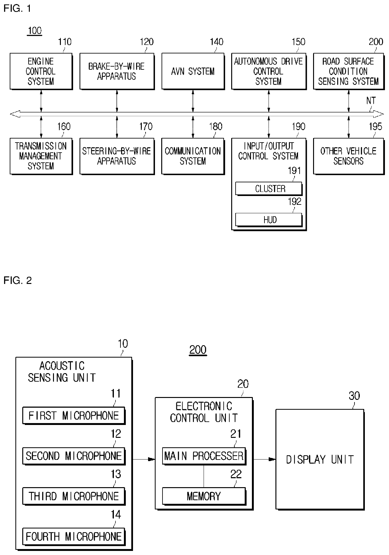
[0033]FIG. 1 illustrates various electronic apparatuses of a vehicle including a road surface condition sensing system according to an embodiment.

[0034]Specifically, as illustrated in FIG. 1, a vehicle 1 may include an engine control system 110, a brake-by-wire apparatus 120, an audio video navigation (AVN) system 140, an autonomous drive control system 150, a transmission management system (TMS) 160, a steering-by-wir...


PUM

PropertyMeasurementUnit
relative distanceaaaaaaaaaa
surface conditionaaaaaaaaaa
road surface conditionaaaaaaaaaa

Abstract

Disclosed are a road surface condition sensing system and method. The road surface condition sensing system includes an acoustic sensing unit for sensing an acoustic signal of a floor of a vehicle, and a control unit for calculating a feature vector by Fourier transforming the sensed acoustic signal, comparing the calculated feature vector with a plurality of previously stored feature vectors and returning a first feature vector having the smallest relative distance to the calculated feature vector, and outputting a road surface condition corresponding to the first feature vector.

Description

CROSS-REFERENCE TO RELATED APPLICATION(S)[0001]This application claims the benefit of Korean Patent Application No. 2017-0052770, filed on Apr. 25, 2017 in the Korean Intellectual Property Office, the disclosure of which is incorporated herein by reference.BACKGROUND[0002]1. Field[0003]The present disclosure relates to a system and method for sensing road surface condition, and more particularly to a system and method for sensing road surface condition based on noise generated as a tire of a traveling vehicle comes into contact with a road surface.[0004]2. Description of the Related Art[0005]Research on the development of autonomous driving vehicles is continuing today. In an autonomous driving vehicle, the condition of a road surface is an important factor in performing the attitude control of the vehicle in addition to the road situation around the vehicle.[0006]For example, since the degree of friction between a road surface and a vehicle wheel varies depending on wet road surfac...

Claims


Application Information

Patent Timeline
Patent Type & Authority Patents(United States)
IPC IPC(8): G08G1/00G08G1/0962G01N29/44G08G1/04G01N29/14B60R16/02B60W40/06B60W10/18G08G1/16B60W30/14G01N29/04G06N3/04G01N29/46G06N3/063
CPCB60W30/14G01N29/4427G01N29/041B60W40/06G08G1/16G06N3/063G08G1/09626B60W10/18G01N29/46G01N29/14G08G1/163G06N3/04G01H15/00B60R21/01334B60W60/0015B60W50/14G06V20/588
Inventor KIM, SHINWOOKKIM, KI-MANKIM, BEOM-KYUPARK, HA-BIT
Owner HL KLEMOVE CORP
Why Eureka
Try Eureka