Connection device for fluid circuits

a fluid circuit and connection device technology, applied in the direction of couplings, process and machine control, instruments, etc., can solve the problems of loss of working fluid contained, heavy and bulky known connection devices, and structurally complex and therefore particularly expensive, and achieve the effect of less heavy, less bulky, and less expensiv

Active Publication Date: 2020-06-09
LEONARDO SPA
View PDF8 Cites 0 Cited by
  • Summary
  • Abstract
  • Description
  • Claims
  • Application Information

AI Technical Summary

Benefits of technology

[0005]It is an object of the present invention to provide a connection device for fluid circuits which is not affected by the disadvantages of the prior art discussed above, that is to say, which completely avoids the formation of pressure peaks within the circuit as a result of the connection of the two circuit sections, which is less heavy, less bulky, structurally simpler and less expensive than the known SSQD devices, and which makes it possible to disconnect the two circuit sections without causing fluid loss from the circuit.
[0008]In short, the invention is based on the idea of providing a connection device comprising two thermal expansion valves releasably connected directly to each other, each valve being configured to be mounted to the end of a respective circuit section and being shiftable, depending on the fluid temperature sensed by the valve, between an open position and a closed position, in which it allows and prevents fluid flow through the valve, respectively. The use of thermal expansion valves to allow or prevent fluid flow through the device makes it possible to provide a device which has a simple design, is lightweight, not bulky and not expensive, and is therefore suitable for large-scale use.

Problems solved by technology

These known devices have a number of disadvantages, including first of all that, as soon as the two circuit sections have been connected, they generate a pressure wave (the so-called “fluid hammer”) which propagates within the circuit.
Furthermore, the known connection devices are heavy and bulky, as well as structurally complex and therefore also particularly expensive, to such an extent that they are used exclusively in very specific applications, for example in the space industry.
According to this known solution, however, the disconnection of the two first (or of the two second) valves from the circuit section interposed therebetween causes the loss of the working fluid contained in said circuit section, which has to be avoided in the case where the working fluid is a hazardous fluid, for example a toxic, reactive or very hot fluid.
This known solution is therefore not able to allow for the disconnection of two adjacent circuit sections without causing fluid loss from the circuit.

Method used


Image

  • Connection device for fluid circuits
  • Connection device for fluid circuits
  • Connection device for fluid circuits

Examples


Embodiment Construction

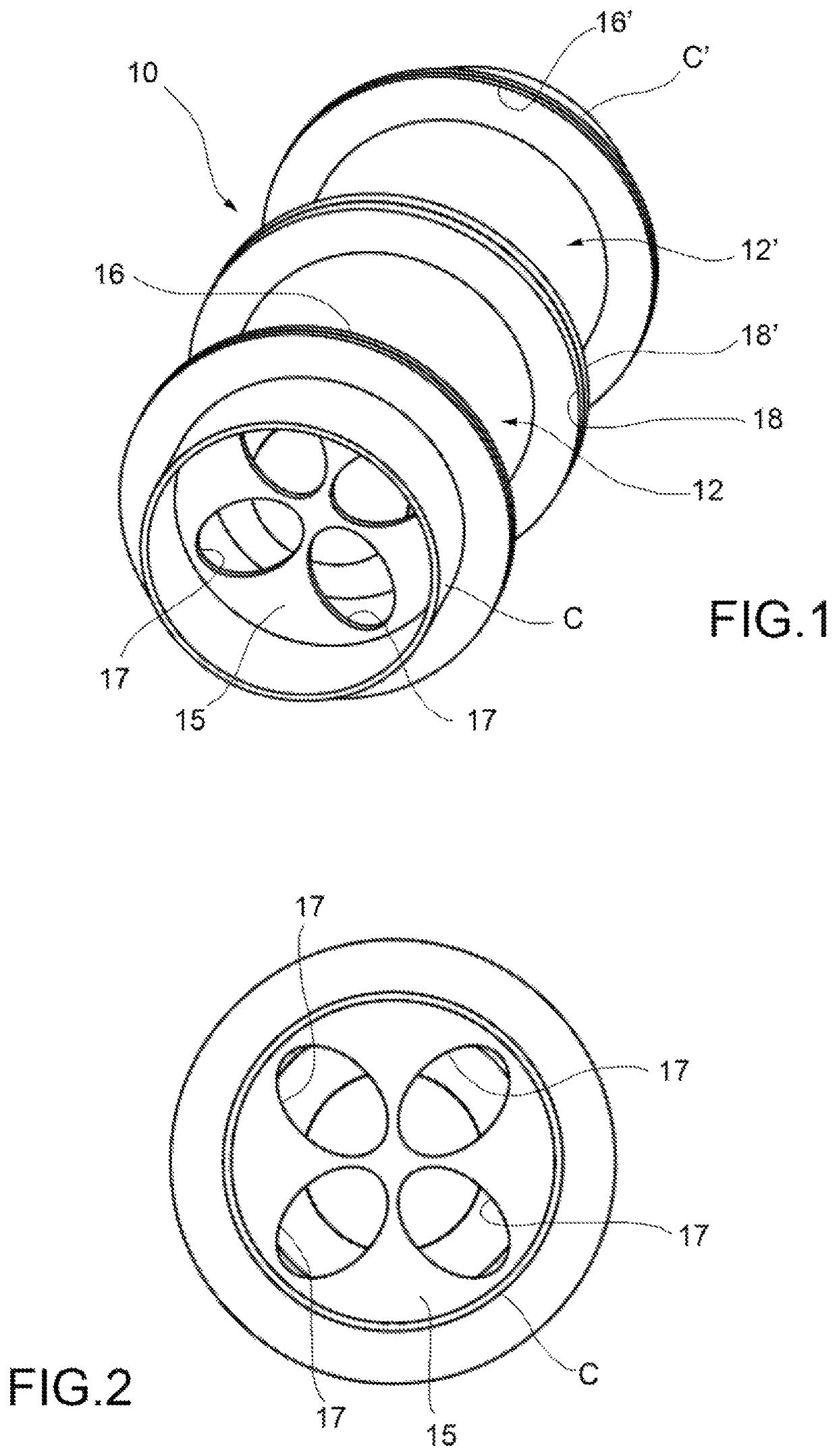
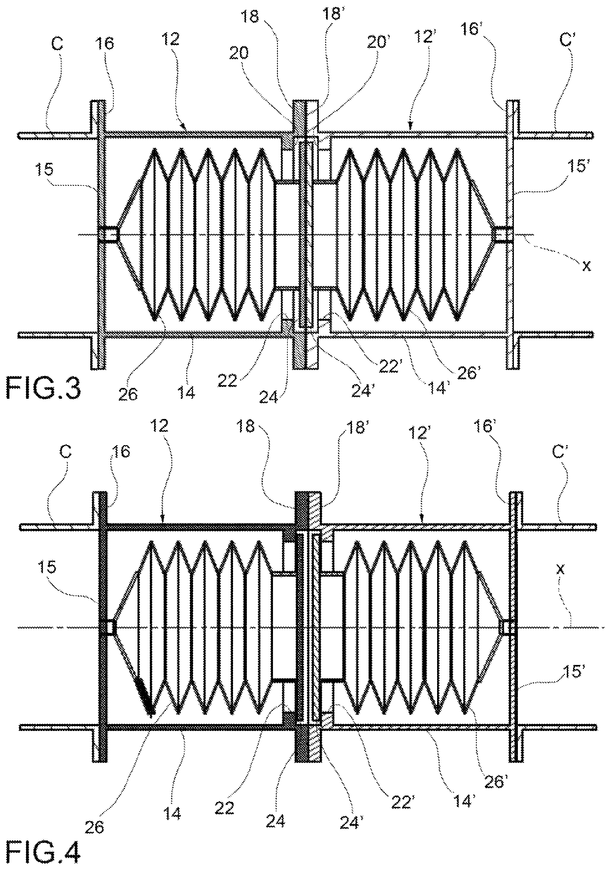
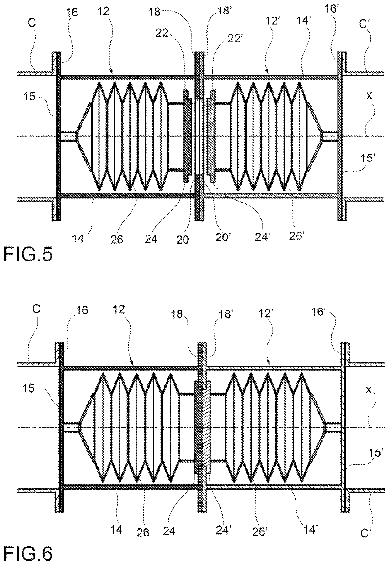
[0017]With reference first to FIGS. 1 to 4, a connection device (hereinafter simply referred to as “device”) for fluid circuits according to a first embodiment of the present invention is generally indicated 10. The device 10 is intended to hydraulically connect two adjacent circuit sections, indicated C and C′, respectively, and is configured to allow disconnection of the two circuit sections C and C′ without causing fluid losses from the circuit, even when at least one of the two circuit sections contains fluid under pressure.

[0018]The device 10 comprises a pair of thermal expansion valves, indicated 12 and 12′, respectively. The valve 12 is mounted, for example by means of screws (not shown), to an end of the first circuit section C, while the valve 12′ is mounted, for example by means of screws (not shown), to an end of the second circuit section C′. The two valves 12 and 12′ are releasably connected directly to each other, for example by means of screws (not shown). Each of the...


PUM


Abstract

The connection device comprises two thermal expansion valves releasably connected directly to each other, each valve being configured to be mounted to an end of a respective section of a fluid circuit and being shiftable between an open position and a closed position, in which it allows and prevents fluid flow through the device, respectively, depending on the fluid temperature.

Description

BACKGROUND OF THE INVENTION[0001]The present invention relates to a connection device for fluid circuits shiftable between a first operating position, in which it allows hydraulic connection of two adjacent sections of the circuit, and a second operating position, in which it allows disconnection of the two adjacent sections of the circuit without causing fluid losses from the circuit, wherein the operation of connecting and disconnecting the two circuit sections can be carried out under load, i.e. with at least one of the two circuit sections containing fluid under pressure.[0002]A connection device for fluid circuits according to the preamble of the accompanying independent claim 1 is known from U.S. Pat. No. 3,291,152.[0003]Connection devices for fluid circuits of the type mentioned above are commonly known by the acronym SSQD (“Self-Sealing Quick Disconnect”). The known SSQD devices typically use mechanical springs to ensure that a closure member is closed during the disconnecti...

Claims


Application Information

Patent Timeline
Patent Type & Authority Patents(United States)
IPC IPC(8): G05D23/02F16L29/04F16L55/10F16L55/07F16K31/00F16L23/00F16L29/00
CPCF16L29/04F16L29/00F16L55/1007F16L23/00F16K31/002F16L55/07G05D23/025F16L37/30
Inventor MOSCATELLI, ANTONIO
Owner LEONARDO SPA
Why Eureka
Try Eureka