Eureka AIR delivers breakthrough ideas for toughest innovation challenges, trusted by R&D personnel around the world.

Knife assembly

a knife and assembly technology, applied in the field of knife assembly, can solve the problems of weighing hundreds of kilograms, and causing hazardous situations, and achieve the effects of reducing the weight of the knife blade, reducing the risk of injury, and reducing the effective thickness of the knife blad

Active Publication Date: 2018-08-02
MEINAN MASCH WORKS INC
View PDF5 Cites 2 Cited by
  • Summary
  • Abstract
  • Description
  • Claims
  • Application Information

AI Technical Summary

Benefits of technology

The invention provides a knife assembly with a thinner blade that is easier to handle and maintains the proper position between the blade and the adjusting bolt. This reduces the weight of the knife.

Problems solved by technology

According to a conventional practice, removal, transportation and installation of a knife assembly have been carried out by using lifting equipment or the like because the knife blade is too heavy to carry by hands and hence laborious and dangerous to do so.
As mentioned above, a knife blade is generally extremely heavy, weighing hundreds of kilograms.
If the above operations to handle a heavy knife assembly is performed quickly in order to increase the working efficiency, it may invite a hazardous situation in that the moving knife blade may be brought into contact with maintenance personnel or nearby equipment.
However, a knife blade which is made thinner reduces its effective thickness at position where the adjusting bolt receiving holes are formed and, therefore, the knife blade tend to be deformed or displaced relative to the adjusting bolts under the influence of external force acting on the knife blade during veneer cutting by the veneer lathe.
Consequently, the dimension between the top surface of the adjusting bolt head and the cutting edge of the knife blade, which correspond to the desired knife height, may be altered, with the result that veneer of the required quality may not be produced.

Method used


Image

  • Knife assembly
  • Knife assembly
  • Knife assembly

Examples


first embodiment

[0030]The following will describe a knife assembly according to the present invention with reference to FIGS. 1 through 6. It is noted that the knife assembly according to the embodiments of the invention is of a type that is applicable to a rotary veneer lathe.

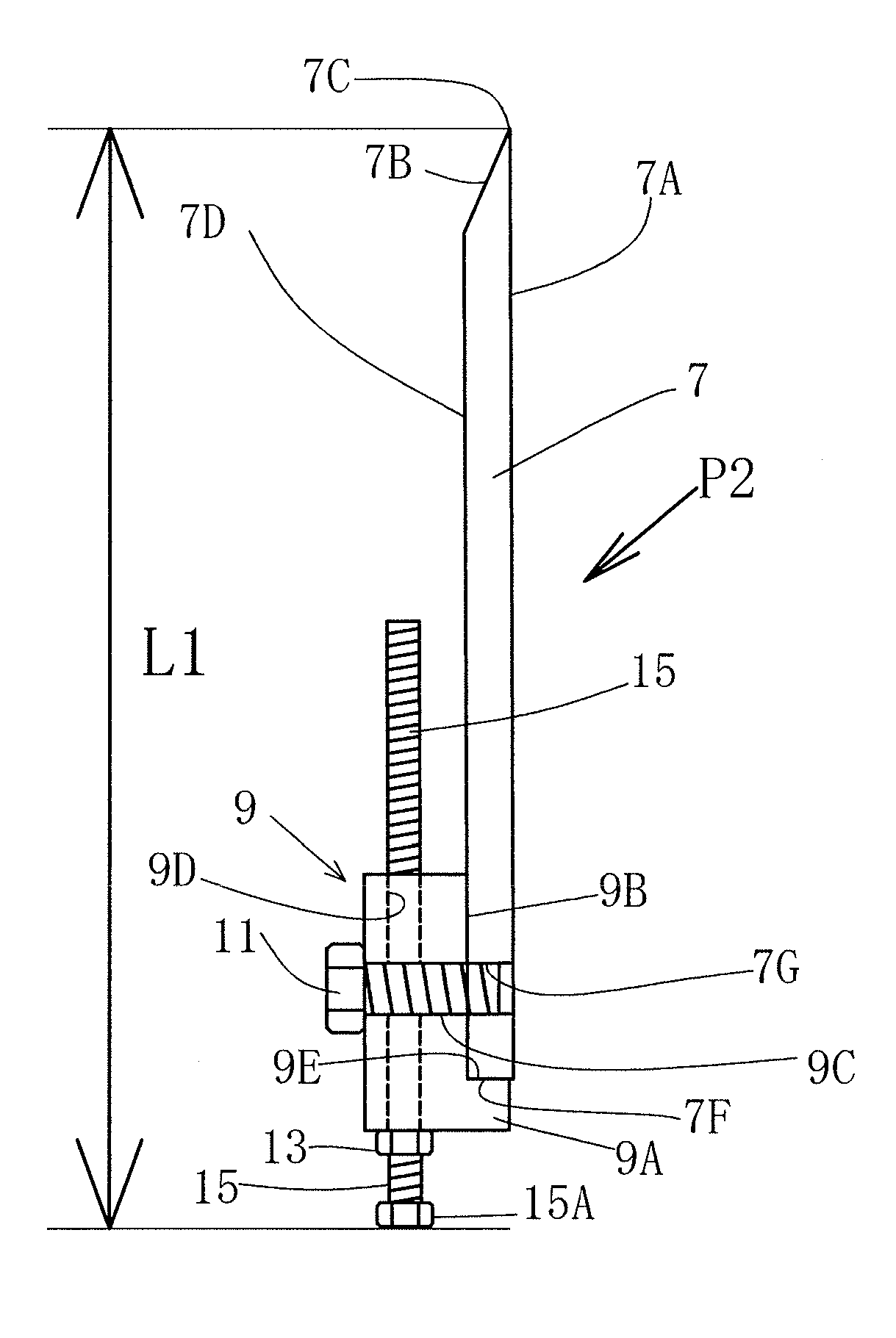
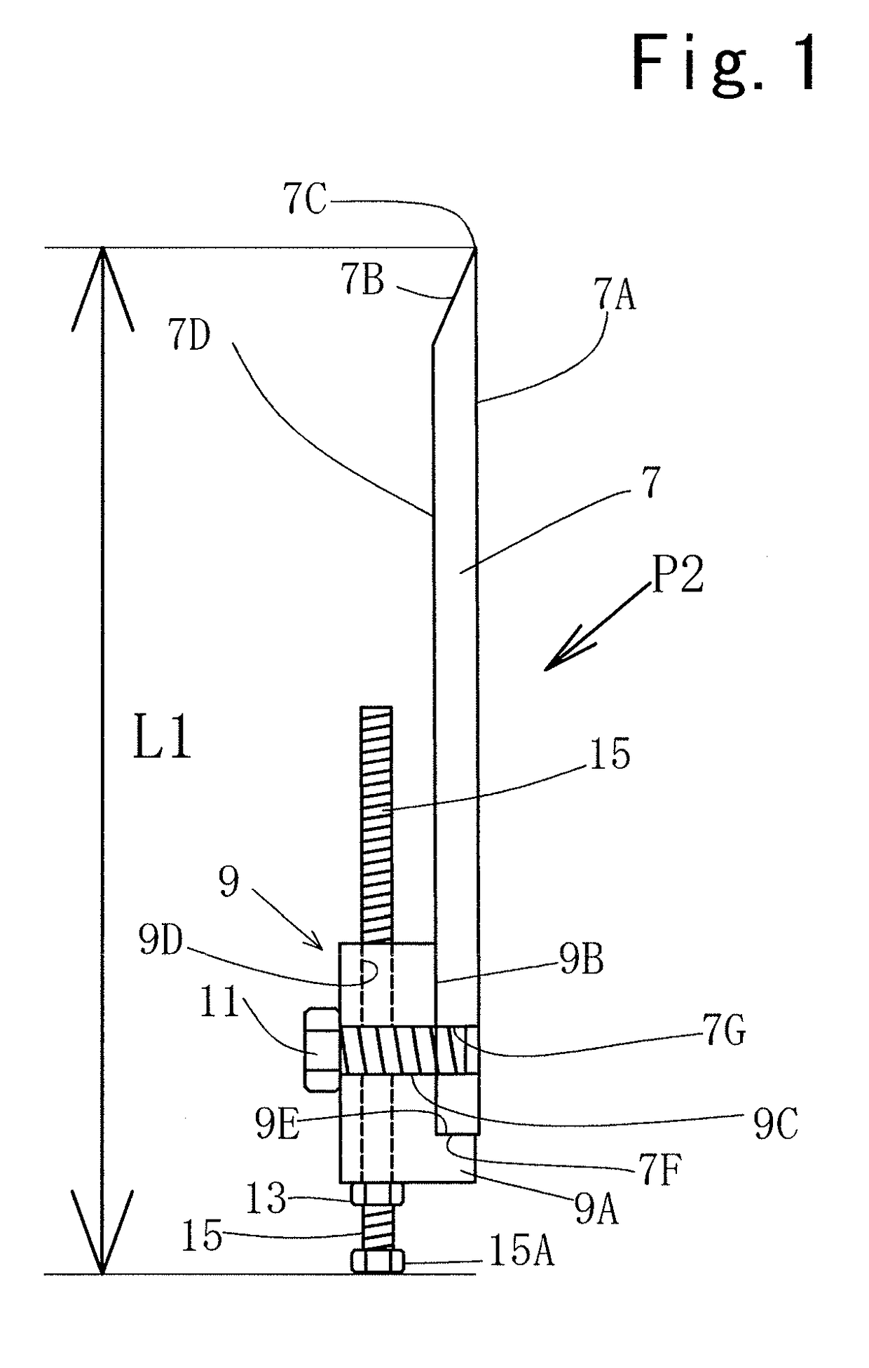
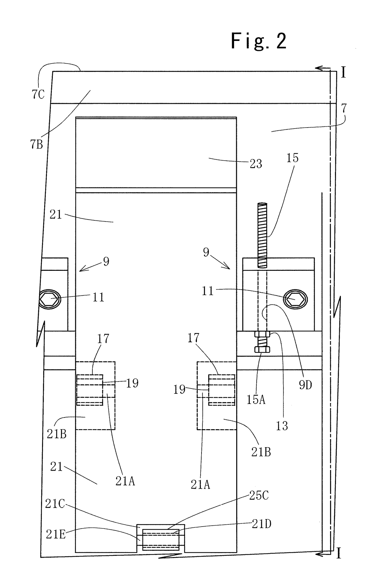
[0031]Referring to FIG. 1, there is shown a knife assembly P2 according to the first embodiment of the present invention. The knife assembly P2 includes a knife blade 7, a plurality of knife blade holders 9 (only one holder shown in the drawing) and a knife height adjusting bolt 15 with a lock nut 13. The knife blade 7 has a first surface 7D and a second surface 7A formed across the thickness of the knife blade 7 and extending parallel to each other, a bevel surface 7B formed on the first surface 7D side of the knife blade 7, a cutting edge 7C formed by the second surface 7A and the bevel surface 7B, and a base end surface 7F extending opposite from and parallel to the cutting edge 7C. The knife blade 7 has a length or the di...

second embodiment

[0041]a knife assembly according to the present invention will now be described with reference to FIGS. 7 through 10. Coordinate axes L, H and T appear in FIGS. 7, 8 and 9, wherein L represents the longitudinal direction, H the height direction and T the thickness direction of the knife blade 37, respectively.

[0042]Referring firstly to FIG. 7, there is shown in perspective view a knife blade holder 30 for a knife assembly P3 (FIGS. 9 and 10) of the second embodiment. The knife blade holder 30 includes a holder block 31 having therein a cutout void portion and a bolt adjusting bolt 35. Specifically, the holder block 31 is generally of a cuboid shape having formed therein a cutout void portion in the form of a recess 31A having three adjoining surfaces 31D, 31F and 31G. The surface 31F has a height L3 and a length L4 and extends parallel to the first surface 37D of the knife blade 37 when the holder block 31 and the knife blade 37 are assembled together into the knife assembly P3 show...


PUM


Abstract

A knife assembly for use in a veneer cutting machine such as a rotary veneer lathe and a veneer slicer includes a knife blade, a knife blade holder and a knife adjusting bolt with a lock nut. The knife blade holder includes a holder block having formed therethrough a threaded hole through which the knife adjusting bolt is adjustably inserted. The holder block has a first support surface that is in supporting contact with a part of one surface of the knife blade on the side thereof where a bevel face of the knife blade is formed and a second support surface that is in supporting contact with a part of a base end surface located opposite from and extending parallel to a cutting edge of the knife blade.

Description

FIELD OF THE INVENTION[0001]The present invention relates to a knife assembly for use in a veneer cutting machine such a rotary veneer lathe and a veneer slicer.BACKGROUND OF THE INVENTION[0002]Referring to FIG. 11, there is shown in a fragmentary side view of a part of a typical rotary veneer lathe which is disclosed in the Japanese Patent No. 3,689,132. Specifically, the drawing shows a knife blade 57 that is fixedly mounted on a knife carriage 55 of a rotary veneer lathe that is movable toward a log or a wood block 51 held and rotated by spindles (not shown) for a distance corresponding to the thickness of veneer sheet 53 to be peeled by the veneer lathe for each rotation of the wood block 51. The knife blade 57 has at the tip end thereof a cutting edge 57C that is formed by a surface 57A and a bevel surface 57B of the knife blade 57. The knife blade 57 fixed on the knife carriage 55 and ready for veneer peeling operation need be precisely set so that the cutting edge 57C is posi...

Claims


Application Information

Patent Timeline
Patent Type & Authority Applications(United States)
IPC IPC(8): B26D7/26B27L5/02
CPCB26D7/2628B27L5/025B26D7/2614B27L5/02B26D1/02B26D3/28
Inventor KOIKE, MASARU
Owner MEINAN MASCH WORKS INC
Why Eureka
Eureka Blog
Learn More