Portable electronic device

a portable electronic device and electronic device technology, applied in the field of portable electronic devices, can solve the problems of reducing the heat dissipation efficiency of the portable electronic device, shortening the working life of each component etc., to improve the heat dissipation efficiency of the portable electronic device, shorten the working life of each component, and reduce the possibility of causing a crash

Active Publication Date: 2020-06-09
QUANTA COMPUTER INC
View PDF26 Cites 6 Cited by
  • Summary
  • Abstract
  • Description
  • Claims
  • Application Information

AI Technical Summary

Benefits of technology

[0007]With the structure described in the above embodiments, the portable electronic device can be switched to provide more ventilation openings, thereby improving the heat dissipation efficiency of the portable electronic device, reducing the possibility of causing crash and shortening the working life of each component of the portable electronic device. In addition, since the portable electronic device is already formed with at least one ventilation opening, the portable electronic device can choose to omit a fixing opening thereon, so that the overall thickness of the portable electronic device can be improved.

Problems solved by technology

However, when the portable electronic device is in the configuration with a reduced overall structure, the heat dissipation efficiency of the portable electronic device might be reduced, so that the portable electronic device requires auxiliary fans for actively removing the thermal energy in the portable electronic device.
Although the auxiliary fans are installed in the portable electronic device, however, if the heat dissipation efficiency of the portable electronic device cannot be effectively improved, the portable electronic device in a high temperature environment in a long-term not only can cause crash easily, but also shorten the working life of each component of the portable electronic device.

Method used


Image

  • Portable electronic device
  • Portable electronic device
  • Portable electronic device

Examples


Embodiment Construction

[0020]Reference will now be made in detail to the present embodiments of the disclosure, examples of which are illustrated in the accompanying drawings. Wherever possible, the same reference numbers are used in the drawings and the description to refer to the same or like parts. According to the embodiments, it will be apparent to those skilled in the art that various modifications and variations can be made to the structure of the disclosure without departing from the scope or spirit of the disclosure.

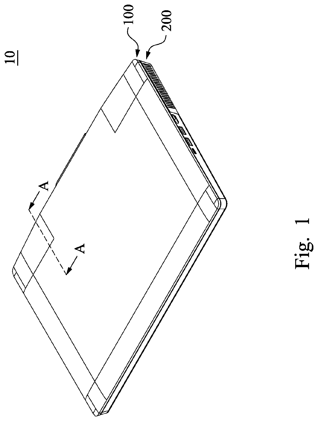
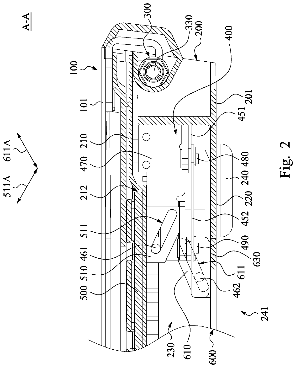
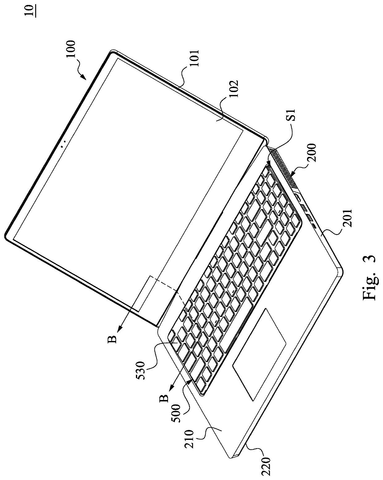
[0021]Reference is now made to FIG. 1 to FIG. 4, in which FIG. 1 is a perspective view showing a portable electronic device 10 in a closed state according to one embodiment of the disclosure, FIG. 2 is a partial cross-sectional view of the portable electronic device 10 along a line A-A of FIG. 1, FIG. 3 is a perspective view showing the portable electronic device 10 of FIG. 1 in an unfolded state, and FIG. 4 is a partial cross-sectional view of the portable electronic device 10 along ...


PUM


Abstract

A portable electronic device includes a first component, a second component, a pivoting device, a cover member and a linkage module. The second component is pivotally coupled to the first component through a pivoting device. The second component has an internal space and a sunken portion. The sunken portion is in communication with the internal space. The cover member is movably embedded in the sunken portion. The linkage module is coupled to the pivoting device and the cover member for selectively pushing the cover member out of the sunken portion with the movement of the pivoting device.

Description

RELATED APPLICATIONS[0001]This application claims priority to Taiwan Application Serial Number 107139549, filed Nov. 7, 2018, which is herein incorporated by reference.BACKGROUNDField of Disclosure[0002]The disclosure relates to a portable electronic device. More particularly, the disclosure relates to a portable electronic device having hidden ventilation openings.Description of Related Art[0003]With the improvement of technology, a portable electronic device (e.g., notebook computer) is developed in a trend of lightweight, small size and higher computing speed. However, when the portable electronic device is in the configuration with a reduced overall structure, the heat dissipation efficiency of the portable electronic device might be reduced, so that the portable electronic device requires auxiliary fans for actively removing the thermal energy in the portable electronic device.[0004]Although the auxiliary fans are installed in the portable electronic device, however, if the hea...

Claims


Application Information

Patent Timeline
Patent Type & Authority Patents(United States)
IPC IPC(8): G06F1/20G06F1/16H05K5/02H05K7/20
CPCH05K7/20136H05K5/0213G06F1/1681G06F1/1616G06F1/203G06F1/1662G06F1/1656
Inventor HSU, SHU-CHENGLAI, KU-WUWU, HSIN-ISHIH, CHIEN-YU
Owner QUANTA COMPUTER INC
Why Eureka
Try Eureka