Electronic cigarette

a technology of electronic cigarettes and atomized vapor, which is applied in the direction of engine diaphragms, diaphragm valves, instruments, etc., can solve the problems of unpleasing user's burning taste, liquid leakage problems, and difficulty in precise control, and achieve enhanced taste of atomized vapor

Active Publication Date: 2020-06-16
MICROJET TECH
View PDF18 Cites 0 Cited by
  • Summary
  • Abstract
  • Description
  • Claims
  • Application Information

AI Technical Summary

Benefits of technology

[0009]An object of the present invention provides an electronic cigarette. The cooperation of a fluid transportation device and an atomizer forms a controllable switch element. The amount of the cigarette liquid to be transferred to the infiltration part of the atomizer is precisely controlled by the controllable switch element. Consequently, the taste of the atomized vapor is enhanced, and the liquid leakage problem is solved.
[0010]Another object of the present invention provides an electronic cigarette for allowing the user to inhale a great amount of atomized vapor quickly. The electronic cigarette includes an airflow sensor and an air pressure sensor. The air pressure sensor issues a detection signal to the control module according to the result of detecting the pressure of the airflow. According to the detection signal, a control module adjusts the speed of atomizing the cigarette liquid and the speed of providing the cigarette liquid. That is, the control signal from the control module is adjusted according to the detection signal. Since the driving frequency of the fluid transportation device and the driving power of the heater module are correspondingly changed according to the control signal, the speed of atomizing the cigarette liquid and the speed of providing the cigarette liquid are adjusted. Consequently, the user can inhale a great amount of atomized vapor quickly, or the user can inhale the same amount of atomized vapor.

Problems solved by technology

Firstly, it is difficult to precisely control the amount of the cigarette liquid to be transferred to the infiltration part 42 through the communication part 431 of the liquid transfer part 43. Consequently, the cigarette liquid is not uniformly absorbed by the infiltration part 42. In case that a site of the infiltration part 42 absorbs a small amount of the cigarette liquid, the liquid drop is not uniformly generated. After the liquid drop of the cigarette liquid is heated by the electric heater 41, the atomized vapor has a burning taste that is unpleasing to the user.
Secondly, since the amount of the cigarette liquid to be transferred to the infiltration part 42 cannot be precisely controlled, another problem occurs. Especially when the mouthpiece 9 faces up, the force of gravity continuously transfers the cigarette liquid from the liquid container 52 to the infiltration part 42. Once the cigarette liquid absorbed by the infiltration part 42 reaches a saturation state, the cigarette liquid drops down to the bracket 7 and the intake-and-electric-connection element 10. Then, the cigarette liquid drops down through the sensing unit 3 and leaks out from the at least one inlet 1c. Meanwhile, a liquid leakage problem occurs.
Moreover, there are some differences between the electronic cigarettes and the real cigarettes.
However, while the user smokes the conventional electronic cigarette, the electric power to be transmitted to the electric heater and the heating speed cannot be adjusted.
Since the cigarette liquid of the conventional electronic cigarette is provided according to a siphon effect, the speed of providing the cigarette liquid is too slow.
Under this circumstance, the amount of the atomized vapor is insufficient or the atomized is burnt out.
That is, the conventional method of atomizing the cigarette liquid of the electronic cigarette still has some drawbacks.
The above problems lead to significant differences between the real cigarette and the electronic cigarette.

Method used


Image

  • Electronic cigarette
  • Electronic cigarette
  • Electronic cigarette

Examples


Embodiment Construction

[0036]The present invention will now be described more specifically with reference to the following embodiments. It is to be noted that the following descriptions of preferred embodiments of this invention are presented herein for purpose of illustration and description only. It is not intended to be exhaustive or to be limited to the precise form disclosed.

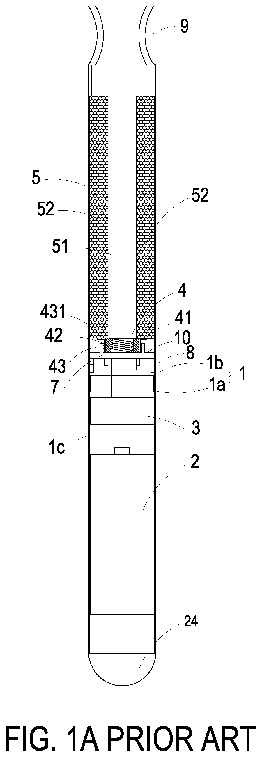
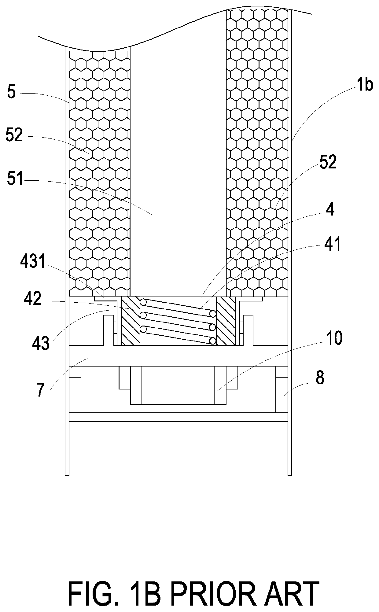
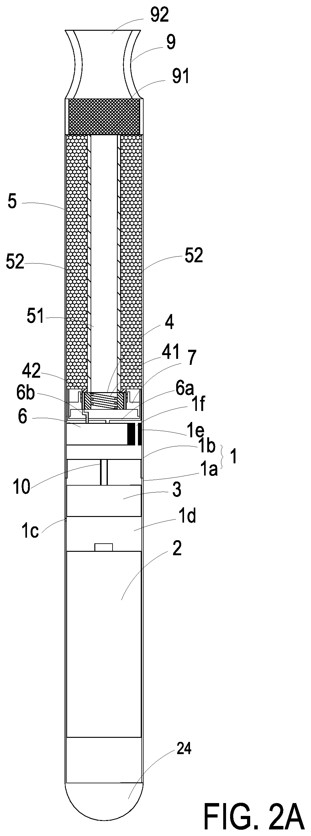
[0037]FIG. 2A is a schematic cross-sectional view illustrating an electronic cigarette according to an embodiment of the present invention. FIG. 2B is a schematic cross-sectional view illustrating some components near the power supply device of the electronic cigarette according to the embodiment of the present invention. FIG. 2C is a schematic cross-sectional view illustrating some components near the atomizer of the electronic cigarette according to the embodiment of the present invention. As shown in FIGS. 2A, 2B and 2C, the electronic cigarette of the present invention comprises a casing 1, a power supply device 2, a sensing ...


PUM


Abstract

An electronic cigarette includes a power supply device, an atomizer, a liquid storage structure, a fluid transportation device and a sensing unit. The atomizer includes an electric heater. The liquid storage structure includes a passageway and a liquid container for storing cigarette liquid. The fluid transportation device is in communication with the liquid container and the atomizer for transferring the cigarette liquid to the atomizer at a certain amount. Consequently, an atomized vapor is generated. The sensing unit includes an airflow sensor and an air pressure sensor. The power supply device is selectively enabled or disabled according to a result of detecting the airflow by the airflow sensor, and the air pressure sensor issues a detection signal to the control module according to a result of detecting a pressure of the airflow so as to adjust a speed of atomizing the cigarette liquid and the speed of providing the cigarette liquid.

Description

FIELD OF THE INVENTION[0001]The present invention relates to an electronic cigarette, and more particularly to an electronic cigarette with a fluid transportation device.BACKGROUND OF THE INVENTION[0002]Nowadays, electronic cigarettes are widely used to replace the conventional tobacco cigarettes. FIG. 1A is a schematic cross-sectional view illustrating a conventional electronic cigarette. FIG. 1B is a schematic cross-sectional view illustrating the structure of the atomizer of the conventional electronic cigarette. As shown in FIGS. 1A and 1B, the electronic cigarette comprises elements which are disposed within a first casing 1a and a second casing 1b after being assembled together. The electronic cigarette comprises the first casing 1a, the second casing 1b, a power supply device 2, a sensing unit 3, an atomizer 4 and a liquid storage structure 5. The first casing 1a and the second casing 1b are thin-wall metal pipes, e.g., stainless steel pipes. The power supply device 2, the se...

Claims


Application Information

Patent Timeline
Patent Type & Authority Patents(United States)
IPC IPC(8): A24F47/00A24F7/04G05B15/02F16K7/00A24F40/485A24F40/10H05B3/44A24F40/50
CPCA24F7/04G05B15/02H05B3/44A24F40/485F16K7/00A24F40/10A24F40/50
Inventor LIAO, JIA-YUMO, LI-PANGCHEN, SHIH-CHANGHUANG, CHI-FENGHAN, YUNG-LUNGTSAI, CHANG-YEN
Owner MICROJET TECH
Why Eureka
Try Eureka