
Printer clean system

a printing machine and clean technology, applied in printing and other directions, can solve the problems of large operation error, increased assembly cost, splashing and contamination, etc., and achieve the effect of avoiding pollution problems, reducing operation errors, and effectively enhancing clean effectivity

Active Publication Date: 2020-06-23
TECO IMAGE SYST
View PDF6 Cites 0 Cited by
  • Summary
  • Abstract
  • Description
  • Claims
  • Application Information

AI Technical Summary

Benefits of technology

The present invention provides a printer clean system that can clean the ink stack and scraper simultaneously using a single power transmission device. The device can rotate to different positions to perform the cleaning actions, resulting in a high cleaning efficiency and avoidance of pollution problems. The system is also designed to use less materials and lower costs, while achieving accurate control over the contact area and cleaning force during cleaning.

Problems solved by technology

No matter what form the ink stack or the scraper assembly is, problems such as splashing and contamination exist.
Specifically, since the ink stack and the scraper assembly are independently controlled to perform ink extraction and pollution scraping, and the structures are independent and complicated, the operation error is larger.
In addition, the ink stack and the scraper assembly that operate independently use more materials, which also makes the assembly cost more.
Furthermore, since the two operate independently, the driving is also carried out independently, and it is difficult to accurately control and adjust the contact area and the cleaning force during cleaning, which may cause unpredictable pollution problems.

Method used


Image

  • Printer clean system
  • Printer clean system
  • Printer clean system

Examples


Embodiment Construction

[0024]The present invention will now be described more specifically with reference to the following embodiments. It is to be noted that the following descriptions of preferred embodiments of this invention are presented herein for purpose of illustration and description only. It is not intended to be exhaustive or to be limited to the precise form disclosed.

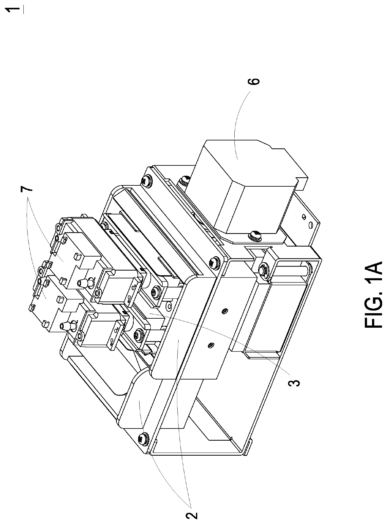
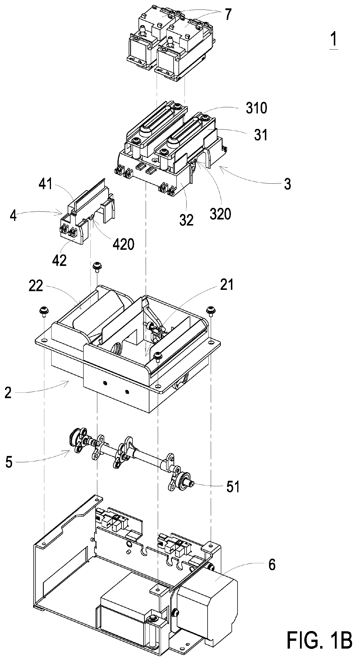
[0025]Please refer to FIG. 1A and FIG. 1B. FIG. 1A schematically illustrates the structure of a printer clean system according to an embodiment of the present invention. FIG. 1B schematically illustrates the exploded view of the printer clean system shown in FIG. 1A. As shown in FIG. 1A and FIG. 1B, a printer clean system 1 according to an embodiment of the present invention includes a base 2, an ink stack assembly 3, a scraper assembly 4, a power transmission device 5 and a driving device 6. The base 2 has a first accommodation groove 21 and a second accommodation groove 22. The first accommodation groove 21 is disposed adjacent...


PUM


Abstract

A printer clean system includes a base, an ink stack assembly, a scraper assembly, a power transmission device and a driving device. The ink stack assembly is disposed on a first accommodation groove. The scraper assembly is disposed on a second accommodation groove. The power transmission device is connected with the driving device, the ink stack assembly, and the scraper assembly. When the power transmission device is rotated to a first angle, the ink stack assembly is brought to an ink stack clean position. When the power transmission device is rotated to a second angle, the scraper assembly is brought to a scraper clean position. When the power transmission device is rotated to a third angle, the ink stack assembly is located at an ink stack return position, and the scraper assembly is located at a scraper return position. Therefore, the pollution can be avoided.

Description

CROSS-REFERENCE TO RELATED APPLICATION[0001]This application claims priority from Taiwan Patent Application No. 107129518, filed on Aug. 23, 2018, the entire contents of which are incorporated herein by reference for all purposes.FIELD OF THE INVENTION[0002]The present invention relates to a clean system, and more particularly to a printer clean system.BACKGROUND OF THE INVENTION[0003]A printer clean system is a system of maintaining the print quality and the nozzle availability. The print clean system mainly includes an ink stack and a scarper assembly.[0004]In general, the ink stack can be classified as a lift type and a swing arm type. The scraper assembly can be classified as a fixed type and a reciprocating type. No matter what form the ink stack or the scraper assembly is, problems such as splashing and contamination exist. Specifically, since the ink stack and the scraper assembly are independently controlled to perform ink extraction and pollution scraping, and the structure...

Claims


Application Information

Patent Timeline
Patent Type & Authority Patents(United States)
IPC IPC(8): B41J2/16B41J2/165
CPCB41J2/16535B41J2/16508B41J2/16511B41J2/16538B41J2/16544
Inventor OU, TENG-YUANCHANG, YU-JEN
Owner TECO IMAGE SYST
Learn More