
Aftertreatment systems and methods for treatment of exhaust gas from diesel engine

a technology of exhaust gas treatment and diesel engine, which is applied in the direction of exhaust treatment electric control, electrical control, machines/engines, etc., can solve the problems of reducing the conversion of nox in the downstream scr and the system

Active Publication Date: 2020-06-23
JOHNSON JOHN H +2
View PDF17 Cites 23 Cited by
  • Summary
  • Abstract
  • Description
  • Claims
  • Application Information

AI Technical Summary

Benefits of technology

The present patent provides systems and methods for aftertreatment systems for diesel engines. The system includes a selective catalytic reduction catalyst on a diesel particulate filter, a reductant injector, a diesel oxidation catalyst, a selective catalyst reduction catalyst, and a controller to determine the desired oxidation of particulate matter and the desired conversion efficiency of system NOx. The system can also include a second reductant injector positioned between the diesel oxidation catalyst and the selective catalyst reduction catalyst. The method involves determining the desired oxidation rate of particulate matter and the desired conversion efficiency of system NOx, and controlling the flow rate of reductant injected from the reductant injector based on these desired rates and the changes in particulate matter concentration, NOx concentration, and temperature as exhaust gas flows through the system. The technical effects of this patent include improved emissions control and efficiency of aftertreatment systems for diesel engines.

Problems solved by technology

The major factors that limit the performance of such aftertreatment system in terms of NOx reduction are catalyst aging in the SCR-F, ash loading in the SCR-F, transport of the platinum group metals (PGM) from the upstream diesel oxidation catalyst (DOC) to the SCR-F and unfavorable NO2 / NOx ratio to the inlet at the downstream SCR, which can lead to reduction of the NOx conversion of the downstream SCR and the system.

Method used


Image

  • Aftertreatment systems and methods for treatment of exhaust gas from diesel engine
  • Aftertreatment systems and methods for treatment of exhaust gas from diesel engine
  • Aftertreatment systems and methods for treatment of exhaust gas from diesel engine

Examples


Embodiment Construction

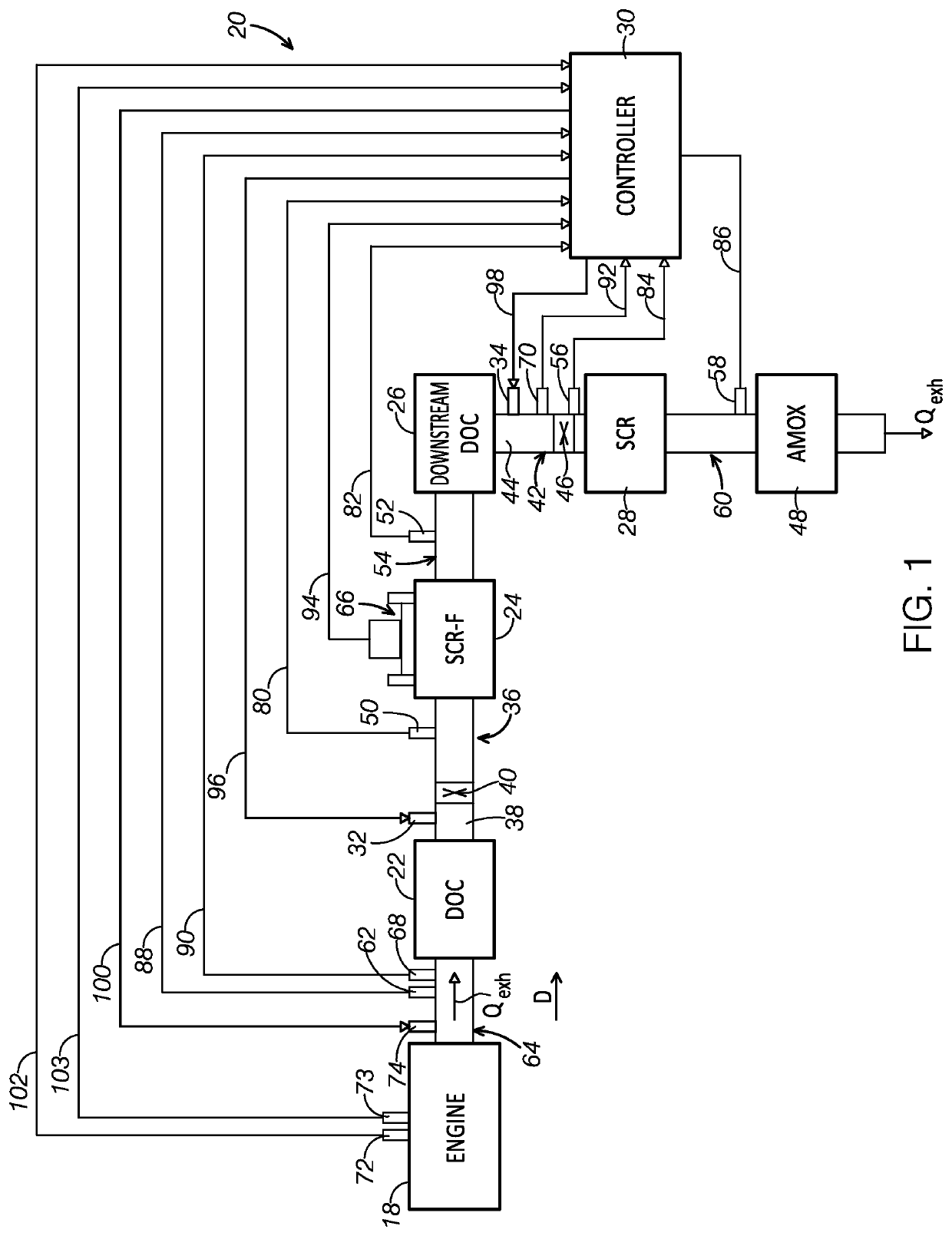
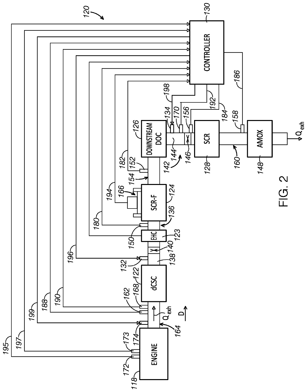
[0030]Various aspects and examples of aftertreatment systems comprising a SCR-F, a downstream DOC, a SCR and two reductant injectors, as well as related methods to operate the aftertreatment systems, are described below and illustrated in the associated drawings. Unless otherwise specified, an aftertreatment system and an engine in accordance with the present teachings, and / or its various components, may contain at least one of the structures, components, functionalities, and / or variations described, illustrated, and / or incorporated herein. Furthermore, unless specifically excluded, the process steps, structures, components, functionalities, and / or variations described, illustrated, and / or incorporated herein in connection with the present teachings may be included in other similar devices and methods, including being interchangeable between disclosed embodiments. The following description of various examples is merely illustrative in nature and is in no way intended to limit the di...


PUM


Abstract

An aftertreatment system to treat exhaust gas from a diesel engine is provided. The aftertreatment system comprises a selective catalytic reduction catalyst on a diesel particulate filter (SCR-F); a first reductant injector connected to an exhaust gas passage upstream of the SCR-F; a downstream diesel oxidation catalyst (DOC) disposed downstream of the SCR-F; a selective catalyst reduction catalyst (SCR) disposed downstream of the downstream DOC; a second reductant injector coupled to an exhaust gas passage positioned between the downstream DOC and the SCR; and a controller to determine a desired particulate matter (PM) oxidation in the SCR-F and a desired system NOx conversion based on engine conditions, and to control a first reductant flowrate from the first reductant injector and a second reductant flowrate from the second reductant injector based on the desired PM oxidation in the SCR-F and the desired system NOx conversion.

Description

FIELD[0001]This disclosure relates to systems and methods for treatment of exhaust gas from a diesel engine. More specifically, the disclosed embodiments relate to systems and methods to control reductant injection into an aftertreatment system of a diesel engine to reduce particulate matter and NOx in the exhaust gas from the diesel engine.INTRODUCTION[0002]Selective catalytic reduction (SCR) technology has been used to reduce NOx emissions from heavy-duty engines. The ultra-low NOx emission standard of 0.02 g / bhp-hr for the heavy-duty diesel engine has been proposed by the California Air Resources Board (CARB). To meet the stringent regulatory NOx emission standards for heavy-duty diesel truck engines, an ultra-low aftertreatment system needs to be developed. For example, an aftertreatment system has been studied that includes an upstream diesel oxidation catalyst (DOC), a selective catalytic reduction catalyst on a diesel particulate filter (SCR-F) and a selective catalyst reduct...

Claims


Application Information

Patent Timeline
IPC IPC(8): F01N3/20F01N3/035F02D41/02F01N9/00F01N3/08F01N3/28
CPCF01N3/0871F01N3/035F01N9/002F01N3/208F02D41/029F01N2900/1611F01N3/2892F01N3/2828F01N3/2066F01N2610/08F01N3/106F01N3/2013F01N9/00F01N11/00F01N2550/02F01N2560/026F01N2560/06F01N2610/02F01N2900/1812F02D41/1445F02D41/1446F02D41/1461F02D41/1465F02D41/1466F01N13/0093Y02T10/12Y02T10/40
Inventor JOHNSON, JOHN H.PARKER, GORDON G.CHUNDRU, VENKATA RAJESH
Owner JOHNSON JOHN H
Learn More