Low luminance lighting

a low luminance, lighting technology, applied in the direction of light source semiconductor devices, fixed installations, lighting and heating apparatus, etc., can solve the problems of high glare, discomfort and distraction, glare from lights, etc., to achieve low luminance, reduce glare, maintain the controllability, directionality, and efficiency of a single point source

Active Publication Date: 2020-06-30
RENESSELAER POLYTECHNIC INST
View PDF23 Cites 0 Cited by
  • Summary
  • Abstract
  • Description
  • Claims
  • Application Information

AI Technical Summary

Benefits of technology

[0004]The subject invention provides novel and advantageous lighting modules and systems, as well as methods of fabricating and methods of using such lighting modules and systems. Lighting modules and systems according to embodiments of the subject invention can be high-efficiency, low-glare lighting modules. Such lighting modules and systems can be low luminance lighting modules or systems. For example, a lighting module or system can utilize a system of multiple layers of efficient optics to spread light from multiple light sources (e.g., a grid of point sources) over a larger luminous surface. The larger luminous surface can maintain the controllability, directionality, and efficiency of a single point source, while significantly reducing the glare. The surface can appear uniformly lit, or substantially uniformly lit, and no dark boundaries may be present between the individual light sources.

Problems solved by technology

Glare from lights, such as oncoming or following car headlights, can be discomforting and distracting.
Because existing car headlights use high-intensity point sources (high luminance, small area) with optics to achieve the required beam spread and light level, glare is high, especially at certain angles.
This can affect comfort and task performance and can lead to a decrease in roadway safety.

Method used


Image

  • Low luminance lighting
  • Low luminance lighting
  • Low luminance lighting

Examples


embodiment 1

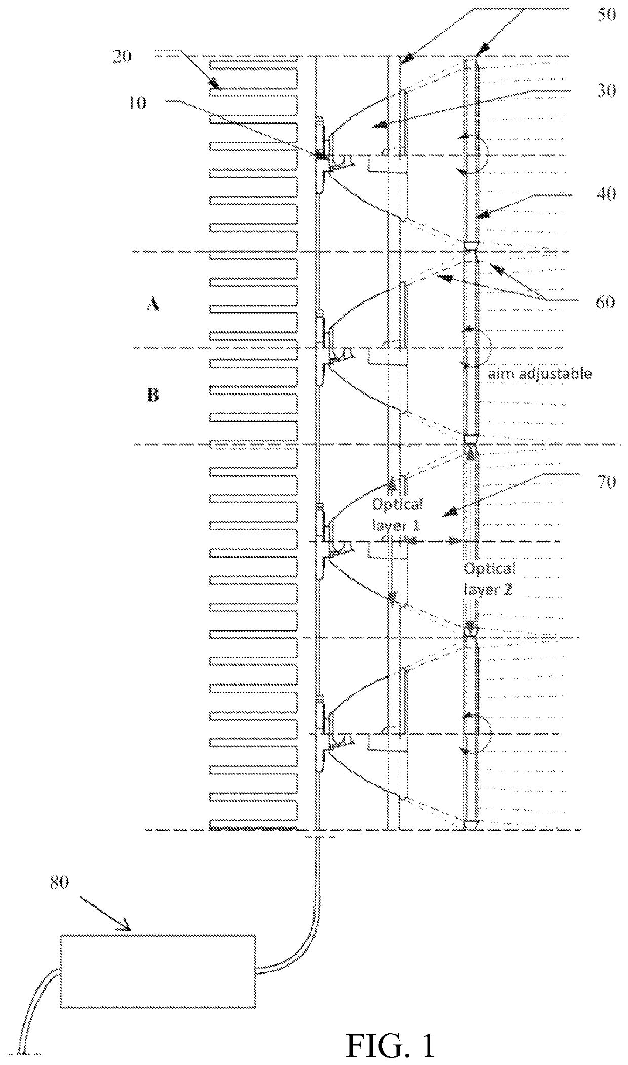
[0045]A lighting system, comprising:

[0046]a plurality of light sources;

[0047]a first optical layer on the plurality of light sources; and

[0048]a second optical layer over the first optical layer,

[0049]wherein the first optical layer is configured to condense light from at least one light source of the plurality of light sources to a smaller beam spread.

embodiment 2

[0050]The lighting system according to embodiment 1, wherein the first optical layer is configured to condense light from all of the light sources of the plurality of light sources to a smaller beam spread.

embodiment 3

[0051]The lighting system according to embodiment 2, wherein the first optical layer is configured to condense light from all of the light sources of the plurality of light sources to a beam spread that matches a full area of the second optical layer.


PUM


Abstract

Novel and advantageous lighting modules and systems are provided. Lighting modules and systems according to embodiments of the subject invention can be low-luminance, high-efficiency, low-glare lighting modules. For example, a lighting system can utilize multiple layers of efficient optics to spread light from multiple light sources (e.g., a grid of point sources) over a larger luminous surface. The larger luminous surface can maintain the controllability, directionality, and efficiency of a single point source, while significantly reducing the glare. The surface can appear uniformly lit, or substantially uniformly lit, and no dark boundaries may be present between the individual light sources.

Description

CROSS-REFERENCE TO RELATED APPLICATIONS[0001]This application is a national stage application of International Patent Application No. PCT / US2014 / 018051, filed Feb. 24, 2014, which claims the benefit of U.S. Provisional Patent Application Ser. No. 61 / 768,684, filed Feb. 25, 2013, both of which are incorporated herein by reference in their entireties.BACKGROUND OF INVENTION[0002]Glare from lights, such as oncoming or following car headlights, can be discomforting and distracting. Existing headlights are perceived as bright point sources by oncoming drivers. Because existing car headlights use high-intensity point sources (high luminance, small area) with optics to achieve the required beam spread and light level, glare is high, especially at certain angles. This can affect comfort and task performance and can lead to a decrease in roadway safety.[0003]Eliminating glare from lights would be very beneficial. For example, eliminating glare from headlights would allow drivers to focus on ...

Claims


Application Information

Patent Timeline
Patent Type & Authority Patents(United States)
IPC IPC(8): B60Q1/14F21S41/143F21S41/20F21V5/00F21V5/04F21S41/32F21S8/08F21S45/47F21V13/04F21V7/00F21V23/04B60Q1/00F21V29/74F21Y105/10F21Y115/10
CPCB60Q1/143F21S41/285F21V5/007F21V5/045F21V5/008F21S41/322F21S41/143F21V29/74F21V23/0457F21Y2115/10F21S8/085F21V7/0083F21Y2105/10F21S45/47F21V13/04B60Q1/0035F21S41/153
Inventor SNYDER, JEREMY DAVIDBULLOUGH, JOHN DONOVANBESENECKER, UTE CHRISTA
Owner RENESSELAER POLYTECHNIC INST
Why Eureka
Try Eureka