
Anti-torque control using matrix of fixed blade pitch motor modules

a fixed blade pitch motor and matrix technology, applied in the field of flight control, can solve problems such as increasing noise, and achieve the effects of reducing or eliminating torque, maximizing thrust, and reducing the noise of the tail rotor

Active Publication Date: 2020-07-07
TEXTRON INNOVATIONS
View PDF93 Cites 7 Cited by
  • Summary
  • Abstract
  • Description
  • Claims
  • Application Information

AI Technical Summary

Benefits of technology

This solution enhances helicopter efficiency, reduces noise and vibration, and increases safety by allowing for independent control of each motor, improving stability and reducing the weight of the aircraft while minimizing the risk of component failures and external threats.

Problems solved by technology

The interference of the vortices may also cause an increase in noise.

Method used


Image

  • Anti-torque control using matrix of fixed blade pitch motor modules
  • Anti-torque control using matrix of fixed blade pitch motor modules
  • Anti-torque control using matrix of fixed blade pitch motor modules

Examples


Embodiment Construction

[0021]While the making and using of various embodiments of the present invention are discussed in detail below, it should be appreciated that the present invention provides many applicable inventive concepts that can be embodied in a wide variety of specific contexts. The specific embodiments discussed herein are merely illustrative of specific ways to make and use the invention and do not delimit the scope of the invention.

[0022]To facilitate the understanding of this invention, a number of terms are defined below. Terms defined herein have meanings as commonly understood by a person of ordinary skill in the areas relevant to the present invention. Terms such as “a”, “an” and “the” are not intended to refer to only a singular entity, but include the general class of which a specific example may be used for illustration. The terminology herein is used to describe specific embodiments of the invention, but their usage does not delimit the invention, except as outlined in the claims.

[...


PUM


Abstract

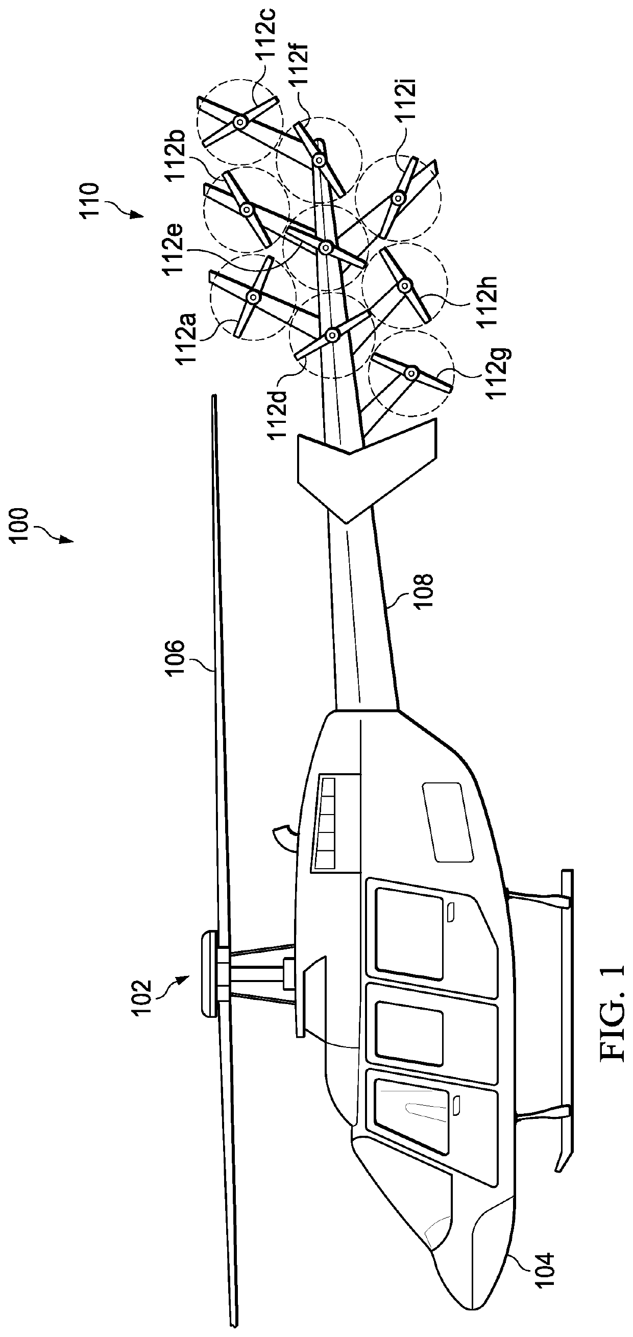
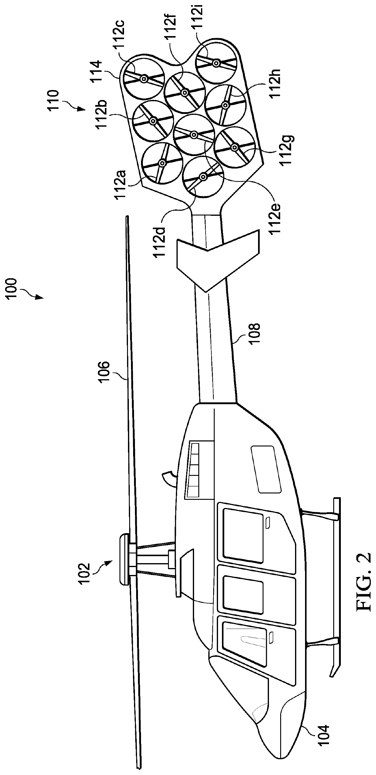
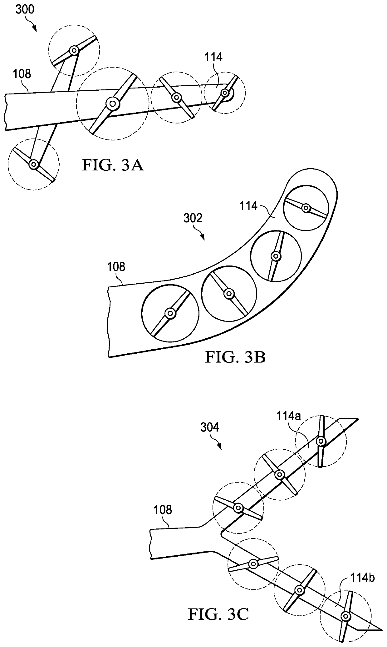
The present invention includes an a plurality of first variable speed motors arranged in a first matrix pattern and mounted on a tail boom of the helicopter; one or more fixed pitch blades attached to each of the plurality of first variable speed motors; and wherein a speed of one or more of the plurality of first variable speed motors is varied to provide an anti-torque thrust.

Description

CROSS-REFERENCE TO RELATED APPLICATIONS[0001]This application claims priority to and is a continuation-in-part patent application of U.S. patent application Ser. No. 15 / 172,811 filed on Jun. 3, 2016, which is hereby incorporated by reference in its entirety.TECHNICAL FIELD OF THE INVENTION[0002]This invention is generally in the field of flight control, and relates specifically to an anti-torque system and control for helicopters.STATEMENT OF FEDERALLY FUNDED RESEARCH[0003]Not applicable.BACKGROUND OF THE INVENTION[0004]Without limiting the scope of the invention, its background is described in connection with anti-torque systems.[0005]Counter-torque tail rotors are often used in helicopters and are generally mounted adjacent to vertical fins that provide for aircraft stability. In such a configuration, the helicopter rotor produces a transverse airflow. Tail rotors can be driven at high angular velocities to provide adequate aerodynamic responses. Sometimes, vortices produced by a ...

Claims


Application Information

Patent Timeline
Patent Type & Authority Patents(United States)
IPC IPC(8): B64C27/82B64C27/04G05D1/08
CPCG05D1/0858B64C27/04B64C27/82B64C2027/8227B64C2027/8209B64C2027/8254B64C2220/00B64C27/12
Inventor FENNY, CARLOSPARSONS, THOMAS DEWEYOLTHETEN, ERIK JOHN
Owner TEXTRON INNOVATIONS
Learn More