
High temperature fluid generator

a generator and fluid technology, applied in water heaters, climate sustainability, heat transfer devices, etc., can solve the problems of long and labor-intensive process of repairing, cleaning and/or replacing convection tubes, incurring prolonged downtime of generators with their attendance costs, etc., to reduce the starting up and cooling off period of the generator, reduce the level of nitrogen oxides, and reduce the effect of effective cooling

Active Publication Date: 2020-07-07
SIMONEAU P I INC
View PDF21 Cites 2 Cited by
  • Summary
  • Abstract
  • Description
  • Claims
  • Application Information

AI Technical Summary

Benefits of technology

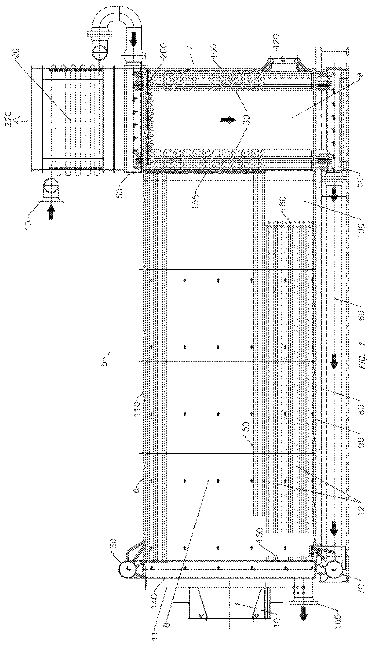
[0013]By allowing the groups of convection tubes to be temporarily moved out of the convection module, inspection, cleaning, maintenance and / or repair of the convection tubes become significantly easier and faster to perform, and allows such operation to be performed in a smaller environment.
[0019]Notably, by placing heating tubes in all the walls of the furnace module, the furnace chamber is effectively cooled by the fluid circulating in the heating tubes. As a large portion of the heat generated by the furnace is transferred to the fluid circulating in the heating tubes, the furnace chamber needs not be insulated using heavy refractory material, making the generator generally lighter.
[0020]In addition, the cooling of the walls of the furnace module with the heating tubes contributes to the reduction of the starting up and cooling off period of the generator, and also contributes to the reduction of the level of nitrogen oxides generated by the combustion process as the furnace temperature would be cooler. Also, such new arrangement, by removing the refractory material, allows for the elimination of hot points on the side walls of the convection module typically found in prior art.
[0021]Hence, a high temperature fluid generator in accordance with the principles of the present invention generally allows an easier access to the convection tubes as they are movable in and out of the convection module. Furthermore, the presence of heating tubes in the floor, ceiling and all walls of the furnace module generally eliminates the need for heavy refractory material to insulate the furnace chamber, making the generator lighter and generally more efficient.

Problems solved by technology

Hence, when one or more convection tube needs to be repaired, cleaned or replaced, the configuration of the convection module makes it very difficult to access the convection tubes.
The repairing, cleaning and / or replacing of convection tubes is thus a long and often labor-intensive process.
This process can further incur prolonged downtimes of the generator with their attendance costs.
In addition, when high volumes of high-temperature fluid are needed, current generators rely on the use of refractory to isolate the walls of the furnace module of the generator.
Such design implies that the generator is both cumbersome and heavy, and may not be adapted for some uses.

Method used


Image

  • High temperature fluid generator
  • High temperature fluid generator
  • High temperature fluid generator

Examples


Embodiment Construction

[0047]A novel high temperature fluid generator will be described hereinafter. Although the invention is described in terms of specific illustrative embodiments, it is to be understood that the embodiments described herein are by way of example only and that the scope of the invention is not intended to be limited thereby.

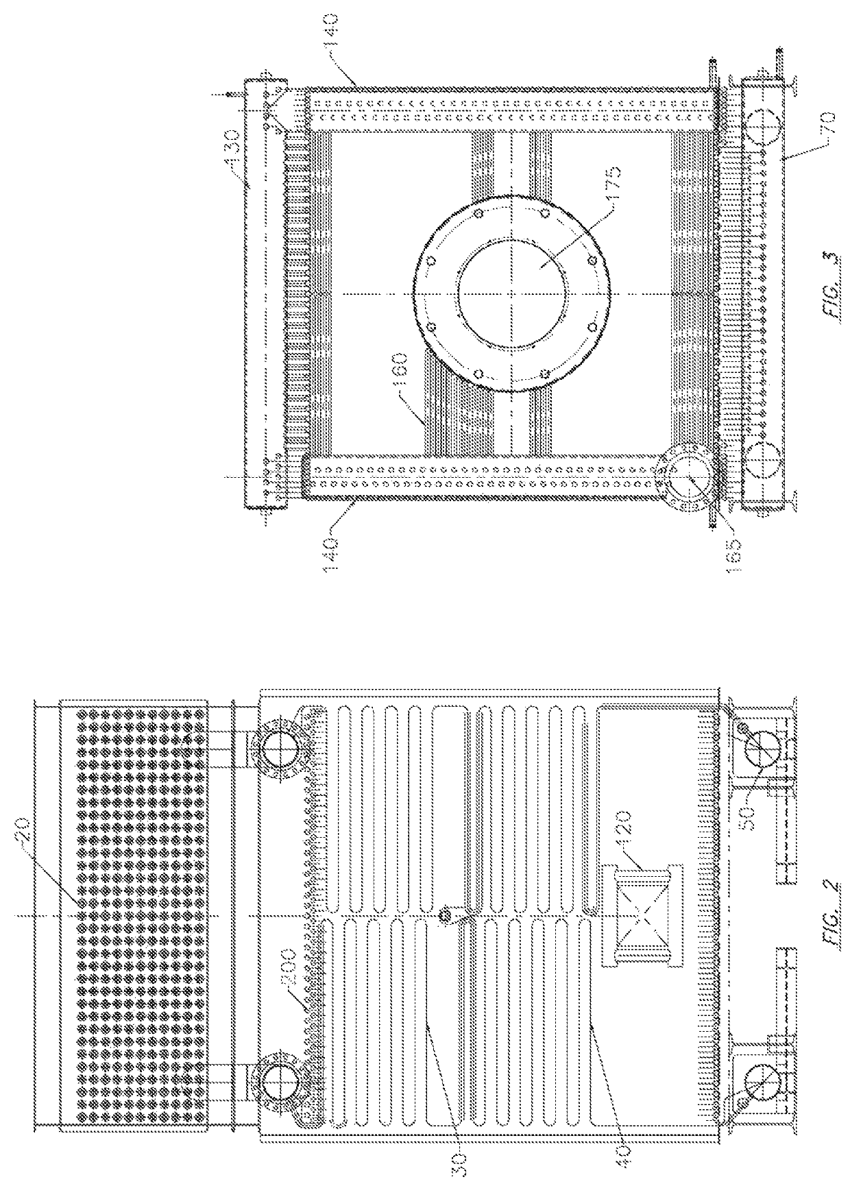
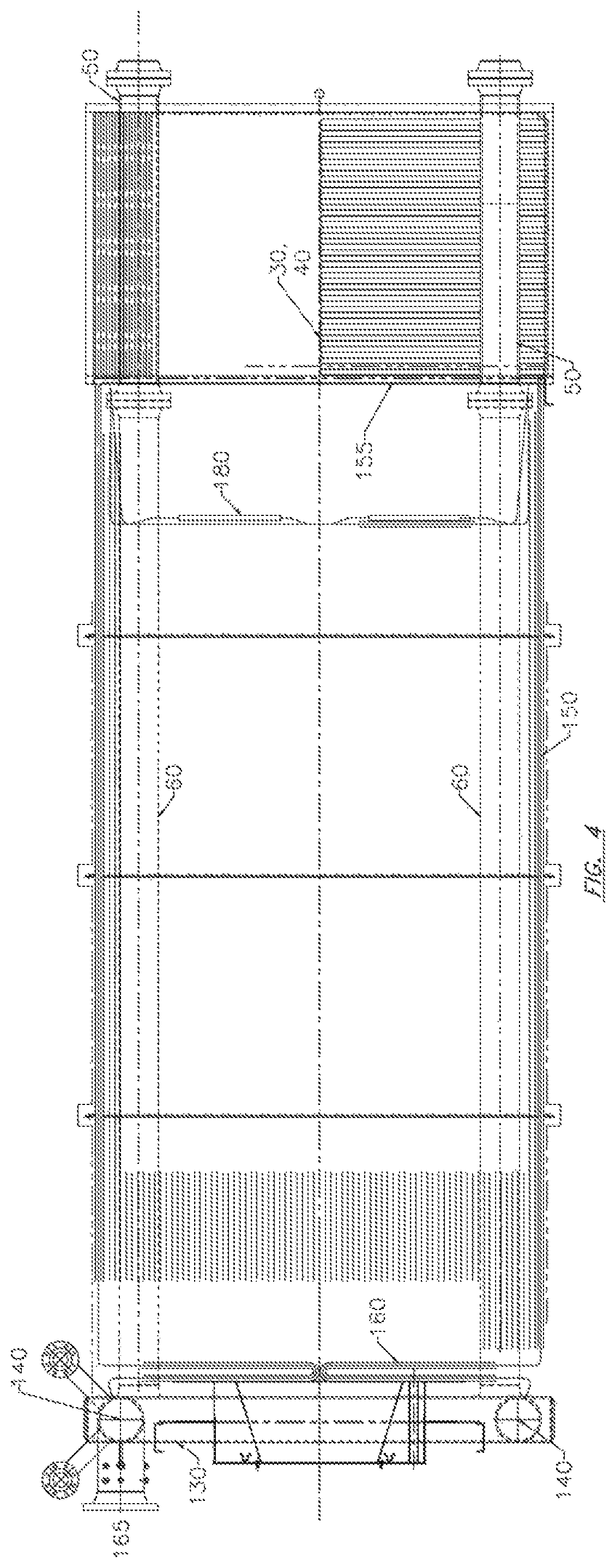
[0048]Referring first to FIG. 1, an embodiment of a generator 5 in accordance with the principles of the present invention is shown. The generator 5 is configured to burn fuel to produce high-temperature (e.g. greater than 120 degrees Celsius) fluids for various purposes (e.g. heating).

[0049]Understandably, various fluids can be heated in generator 5 such as low or high temperature hot water, mixtures of water and glycols, thermal fluids, thermal oils and others. The present generator 5 is generally not limited to any particular fluid.

[0050]Referring to FIG. 1, the generator 5 generally comprises a furnace module 6 and a convection module 7 in communication with the...


PUM


Abstract

A high temperature fluid generator is configured to heat a fluid (e.g. water; thermal oil or the like) to a high temperature (e.g. greater than 250 degrees Fahrenheit or 120 degrees Celsius) using a fuel-burning furnace. The generator generally comprises a furnace module, wherein fuel is burned, and a convection module where the combustion gases are put in contact with a series of fluid-bearing convection tubes. The furnace module comprises a series of fluidly interconnected headers, some of which are also fluidly connected to the convection tubes in the convection modules. The various headers contribute to the overall structure of the generator. The convection tubes are arranged into at least two bundles which are movably mounted in the convection module of the generator such to be movable in and out of the convection module for inspection, cleaning, maintenance and / or repair.

Description

CROSS-REFERENCE TO RELATED APPLICATIONS[0001]The present patent application claims the benefits of priority of U.S. Patent Application No. 61 / 920,001, entitled “High Temperature Fluid Generator” and filed at the United States Patent and Trademark Office on Dec. 23, 2013.FIELD OF THE INVENTION[0002]The present invention generally relates to boilers and other high temperature fluid generators.BACKGROUND OF THE INVENTION[0003]Hot fluid generators are well known in the art and many designs exist. When referring to hot water or hot fluid, reference is generally made to water or fluid having a desired temperature exceeding 250 Fahrenheit (about 120 degrees Celsius). Furthermore, reference is generally made to fluid since most hot fluid generators may be used for heating water but also for heating thermal oils and other fluids.[0004]Existing generators generally comprise a furnace module in which fuel is burned to generate heat, and a convection module connected to the furnace module and c...

Claims


Application Information

Patent Timeline
Patent Type & Authority Patents(United States)
IPC IPC(8): F22D1/20F28G15/00F24H9/14F24H1/14F24H1/40F24H1/41F24H9/06
CPCF24H1/41F24H9/06F22D1/20F24H1/406F24H1/14F28G15/00F24H9/14F28F2280/02Y02B30/108Y02B30/00
Inventor GAUTHIER, REJEANAUDET, ROBERT
Owner SIMONEAU P I INC
Learn More