Check patentability & draft patents in minutes with Patsnap Eureka AI!

Lighting device

a technology of lighting devices and light sources, applied in lighting apparatus, electric lighting sources, electric lighting sources, etc., can solve problems such as delay in communication between local and remote lighting systems, and achieve the effect of increasing communication speeds

Active Publication Date: 2020-07-07
PANASONIC INTELLECTUAL PROPERTY MANAGEMENT CO LTD
View PDF7 Cites 0 Cited by
  • Summary
  • Abstract
  • Description
  • Claims
  • Application Information

AI Technical Summary

Benefits of technology

This solution enables faster communication speeds between different local networks by eliminating the need for internet-based communication, reducing latency and increasing operational efficiency.

Problems solved by technology

This delays communication between the local and remote lighting systems.

Method used


Image

  • Lighting device
  • Lighting device
  • Lighting device

Examples


embodiment 1

(Configuration)

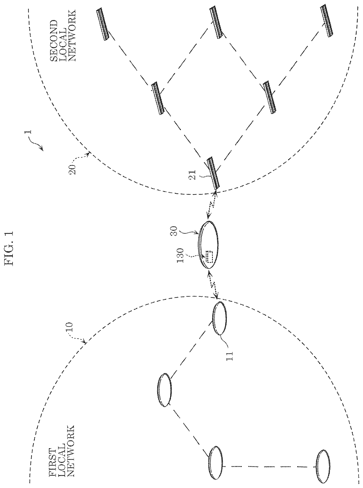
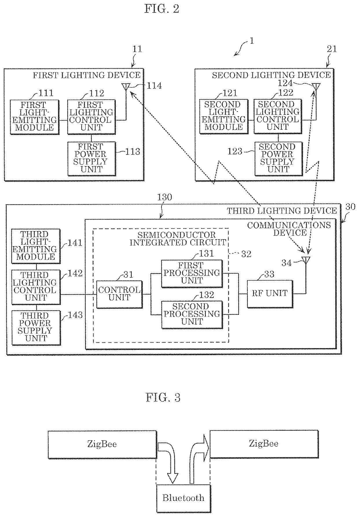
[0021]FIG. 1 schematically illustrates lighting system 1 according to Embodiment 1. FIG. 2 is a block diagram of lighting system 1 according to Embodiment 1.

[0022]As illustrated in FIG. 1, lighting system 1 includes, for example, a plurality of lighting devices and third lighting device 30, each including a wireless communications function. In lighting system 1, a local network of a plurality of lighting devices is formed by adjacent lighting devices wirelessly communicating with each other and forming wireless communication paths. The local network may be formed between lighting devices within a predetermined number of hops. Here, a local network refers to a network of wireless communication paths between lighting devices.

[0023]Lighting system 1 includes first local network 10, second local network 20, and third lighting device 30. When the communications protocol used in first local network 10 and the communications protocol used in second local network 20 are diffe...

embodiment 2

(Configuration)

[0103]Next, the configuration of lighting system 1 according to this embodiment will be described.

[0104]FIG. 6 is a block diagram of lighting system 1 according to Embodiment 2. FIG. 7 illustrates operations performed by communications device 230 of lighting system 1 according to Embodiment 2.

[0105]As illustrated in FIG. 7, in this embodiment, the scan windows for Bluetooth (registered trademark) and ZigBee overlap, unlike in Embodiment 1 in which the scan windows for Bluetooth (registered trademark) and ZigBee are temporally mutually exclusive. Unless stated otherwise, the configuration of communications device 230 according to this embodiment is the same as described in Embodiment 1. Moreover, like elements share like reference signs in the drawings, and repeated detailed description of like elements will be omitted.

[0106]As illustrated in FIG. 6, communications device 230 includes buffer 235 in addition to control unit 31, third communications unit 34, and RF unit ...


PUM


Abstract

A third lighting device connects one or more first lighting devices included in a first local network with one or more second lighting devices included in a second local network different from the first local network. The third lighting device includes: a first processing unit that wirelessly communicates with the one or more first lighting devices via a first communications protocol; a second processing unit that wirelessly communicates with the one or more second lighting devices via a second communications protocol different from the first communications protocol; and a control unit that switches between causing the first processing unit to wirelessly communicate with the one or more first lighting devices and causing the second processing unit to wirelessly communicate with the one or more second lighting devices.

Description

CROSS REFERENCE TO RELATED APPLICATION[0001]This application claims the benefit of priority of Japanese Patent Application Number 2017-229713 filed on Nov. 29, 2017, the entire content of which is hereby incorporated by reference.BACKGROUND1. Technical Field[0002]The present disclosure relates to a lighting device.2. Description of the Related Art[0003]Japanese Unexamined Patent Application Publication (Translation of PCT Application) No. 2017-502475 discloses a lighting system including a local lighting system and a remote lighting system. The local lighting system includes a single light source group, and the remote lighting system includes a different light source group, and uses a wireless communication method different from the method used by the local lighting system. This lighting system communicably connects the local and remote lighting systems via a wide area computing network, including the internet.SUMMARY[0004]With such a lighting system, communication between local and...

Claims


Application Information

Patent Timeline
Patent Type & Authority Patents(United States)
IPC IPC(8): H05B33/08H05B45/20H05B45/24H05B47/19H05B47/10H05B44/00
CPCH05B47/19H05B45/24Y02B20/40H05B47/1985H05B47/1965
Inventor MAEDA, HIKARUKURIHARA, SHINICHIRO
Owner PANASONIC INTELLECTUAL PROPERTY MANAGEMENT CO LTD
Features
  • R&D
  • Intellectual Property
  • Life Sciences
  • Materials
  • Tech Scout
  • Unparalleled Data Quality
  • Higher Quality Content
  • 60% Fewer Hallucinations
Learn More