Clock recovery circuit and electronic device using a clock recovery circuit

Inactive Publication Date: 2007-11-27
NEC CORP
View PDF17 Cites 24 Cited by
  • Summary
  • Abstract
  • Description
  • Claims
  • Application Information

AI Technical Summary

Benefits of technology

[0008]A problem which arises with the technique employing the PLL is that a capacitor used in the loop filter occupies a large area. Such an implementation does not lend itself to a high degree

Problems solved by technology

A problem which arises with the technique employing the PLL is that a capacitor used in the loop filter occupies a large area.
Such an implementation does not lend itself to a high degree of integration.
If communication speed is raised, moreover, a phase comparator and charge pump that operate at high speed become necessary and have the effect of limiting the communication speed.
Consequently, a high-speed VCO is required and a limitation is imposed upon the oscillation frequency of the VCO.
Further, this t

Method used


Image

  • Clock recovery circuit and electronic device using a clock recovery circuit
  • Clock recovery circuit and electronic device using a clock recovery circuit
  • Clock recovery circuit and electronic device using a clock recovery circuit

Examples


Example

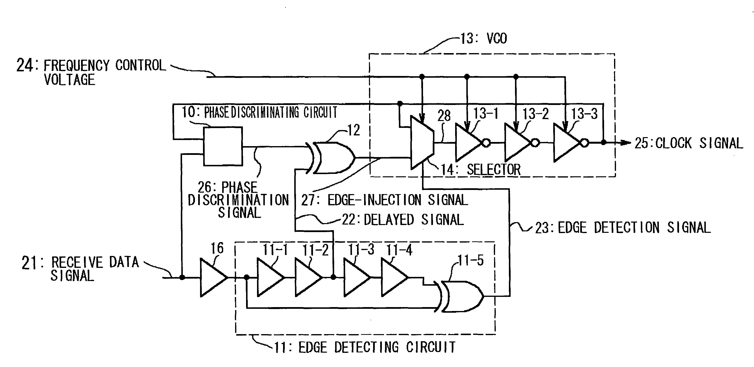
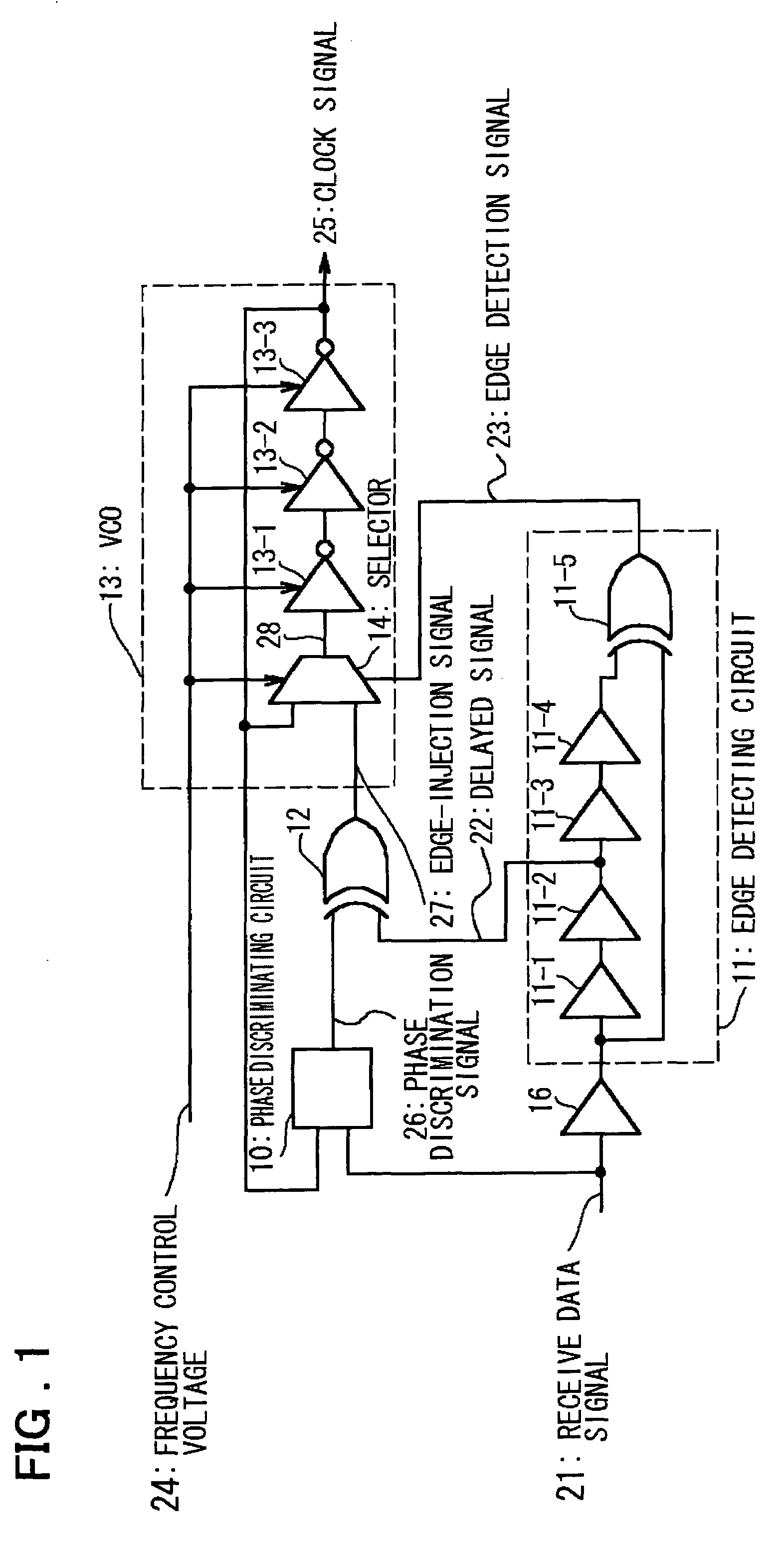
[0036]Preferred embodiments of the present invention will now be described in detail with reference to the drawings. FIG. 1 is a block diagram illustrating a first embodiment of a clock recovery circuit according to the present invention. As shown in FIG. 1, the clock recovery circuit according to this embodiment comprises a phase discriminating circuit 10, an edge detecting circuit 11, an exclusive-OR gate 12 and a VCO 13.

[0037]The phase discriminating circuit 10 discriminates, at every edge of a received data signal 21, phase lead or phase lag of an identically directed edge of a clock signal 25 output from the VCO 13, and outputs a phase discrimination signal 26 indicative of the phase state discriminates.

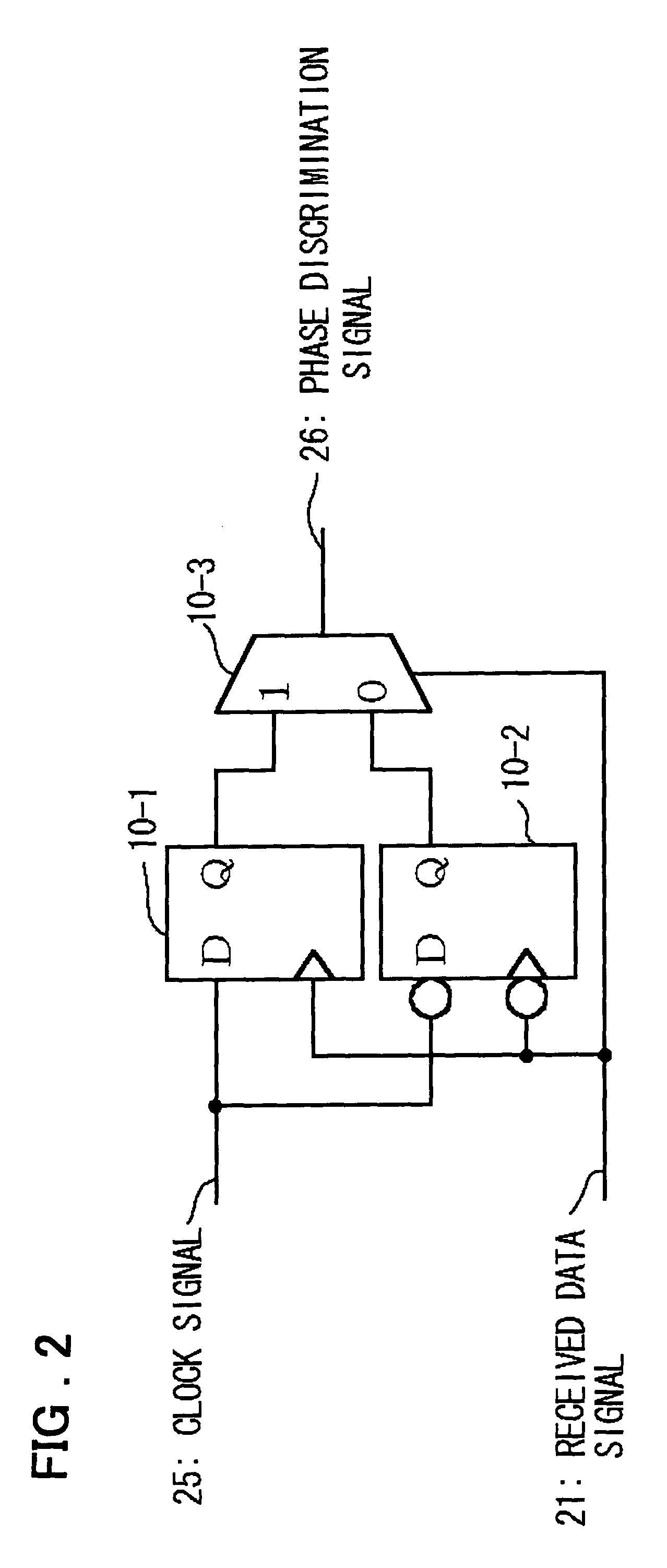
[0038]FIG. 2 is a circuit diagram illustrating an example of the structure of the phase discriminating circuit 10.

[0039]As shown in FIG. 2, the phase discriminating circuit 10 includes a D-type flip-flop (FF1) 10-1 which samples the clock signal 25 with a rising-edge of the rece...

Example

[0050]A second embodiment of a regenerator according to the present invention will now be described.

[0051]In comparison with the clock recovery circuit of the first embodiment shown in FIG. 1, the clock recovery circuit according to the second embodiment is such that the blocks other than the VCO 13 are the same structurally but the internal structure of the VCO 13 is different. Accordingly, in the description of the clock recovery circuit of this embodiment, only the VCO 13 and its related parts will be described in order to avoid prolixity.

[0052]FIG. 4 is a circuit diagram illustrating an example of the structure of the VCO 13 in the clock recovery circuit of this embodiment.

[0053]Referring to FIG. 4, the VCO 13 in the clock recovery circuit of the second embodiment includes a mixer 15, which receives the clock signal 25 and the edge injection signal 27 as inputs, for mixing input signals at a fixed ratio in accordance with the edge detection signal 23 and outputting the mixed sig...


PUM


Abstract

A clock recovery circuit includes a phase discriminating circuit for discriminating, at every edge of a received data signal, phase lead or phase lag of an identically directed edge of the clock signal, and outputting the phase discrimination signal; an edge detecting circuit for detecting edges of the received data signal, outputting an edge detection signal of a fixed pulse width, delaying the received data signal and outputting the delayed signal; an exclusive-OR gate for outputting, as an edge injection signal, an exclusive-OR signal between the phase discrimination signal and delayed signal; and a voltage-controlled oscillator for variably controlling frequency of ring oscillation, injecting the edge injection signal into the loop of ring oscillation, and outputting a clock signal locked to the received data signal.

Description

FIELD OF THE INVENTION[0001]This invention relates to a clock recovery circuit and, more particularly, to a clock recovery circuit for recovering a clock signal from a received data signal and outputting the clock signal.BACKGROUND OF THE INVENTION[0002]Clock recovery circuits are used in interfaces for interconnecting logic ICs and boards in many fields such as personal computers, work stations, network devices, computer peripherals, consumer devices and the like.[0003]Examples of configurations of conventional clock recovery circuits, include one which employs a phase-locked loop (referred to as a “PLL” below), one which receives multiphase clock signals to select among multiphase clock signals a signal of which phase is locked to that of a received data signal, and one which uses a gated voltage-controlled oscillator (referred to as a “gated VCO” below).[0004]A clock recovery circuit that uses a PLL comprises a phase comparator, a charge pump, a loop filter and a voltage-controll...

Claims


Application Information

Patent Timeline
IPC IPC(8): H04L7/00H03K5/00H03K5/1534H03L7/07H03L7/08H03L7/081H03L7/083H03L7/089H03L7/091H03L7/099H04L7/02H04L7/027H04L7/033
CPCH03K5/1534H03L7/07H03L7/0805H03L7/081H04L7/033H03L7/083H03L7/091H03L7/0995H04L7/027H03K2005/00026H03L7/0891H03L7/0812H04L7/0276H03L7/0816H03L7/0807
Inventor KAERIYAMA, SHUNICHIMIZUNO, MASAYUKI
Owner NEC CORP
Why Eureka
Try Eureka