
Endoscope system, processor device, and method for operating endoscope system

a technology of endoscope and processor device, which is applied in the direction of television system, instrument, color signal processing circuit, etc., can solve the problems of inability to accurately align interference with the observation of the observation target, and the position of the halation region to move by a comparably large amount, so as to reduce the false color in the halation region

Active Publication Date: 2020-07-14
FUJIFILM CORP
View PDF16 Cites 2 Cited by
  • Summary
  • Abstract
  • Description
  • Claims
  • Application Information

AI Technical Summary

Benefits of technology

The present invention provides an endoscope system that reduces false colors in a halation region when generating a display image. This is achieved by changing the tone of the halation region when using two images obtained by imaging an observation target by different illumination light beams at different timings. A processor device and method for operating the endoscope system are also provided. The technical effect is to improve the accuracy and reliability of the display image generated by the endoscope system.

Problems solved by technology

Even a slight movement of the observation target may cause the position of the halation region to move by a comparably large amount.
Thus, in the alignment of the observation target, typically, it is not possible to accurately align the position of the halation region.
The false color in the halation region is particularly obvious if a display image in which a tone reflects a calculation result (e.g., difference) of the images used, and may interfere with the observation of the observation target.
However, as described above, it is not possible to prevent generation of a false color when generating a display image by using two images of different colors, which are acquired at different timings.
Therefore, it is not possible to reduce the false color of the halation region.

Method used


Image

  • Endoscope system, processor device, and method for operating endoscope system
  • Endoscope system, processor device, and method for operating endoscope system
  • Endoscope system, processor device, and method for operating endoscope system

Examples


Embodiment Construction

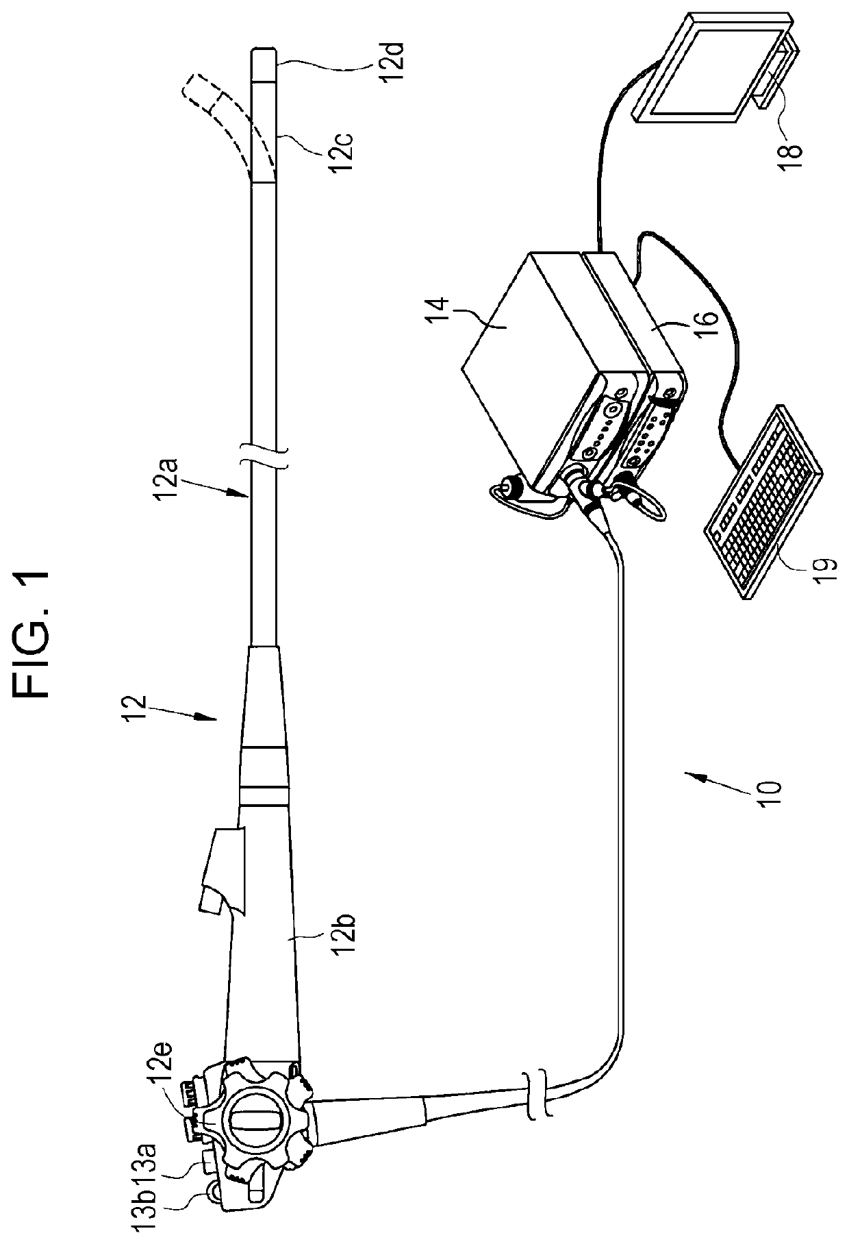
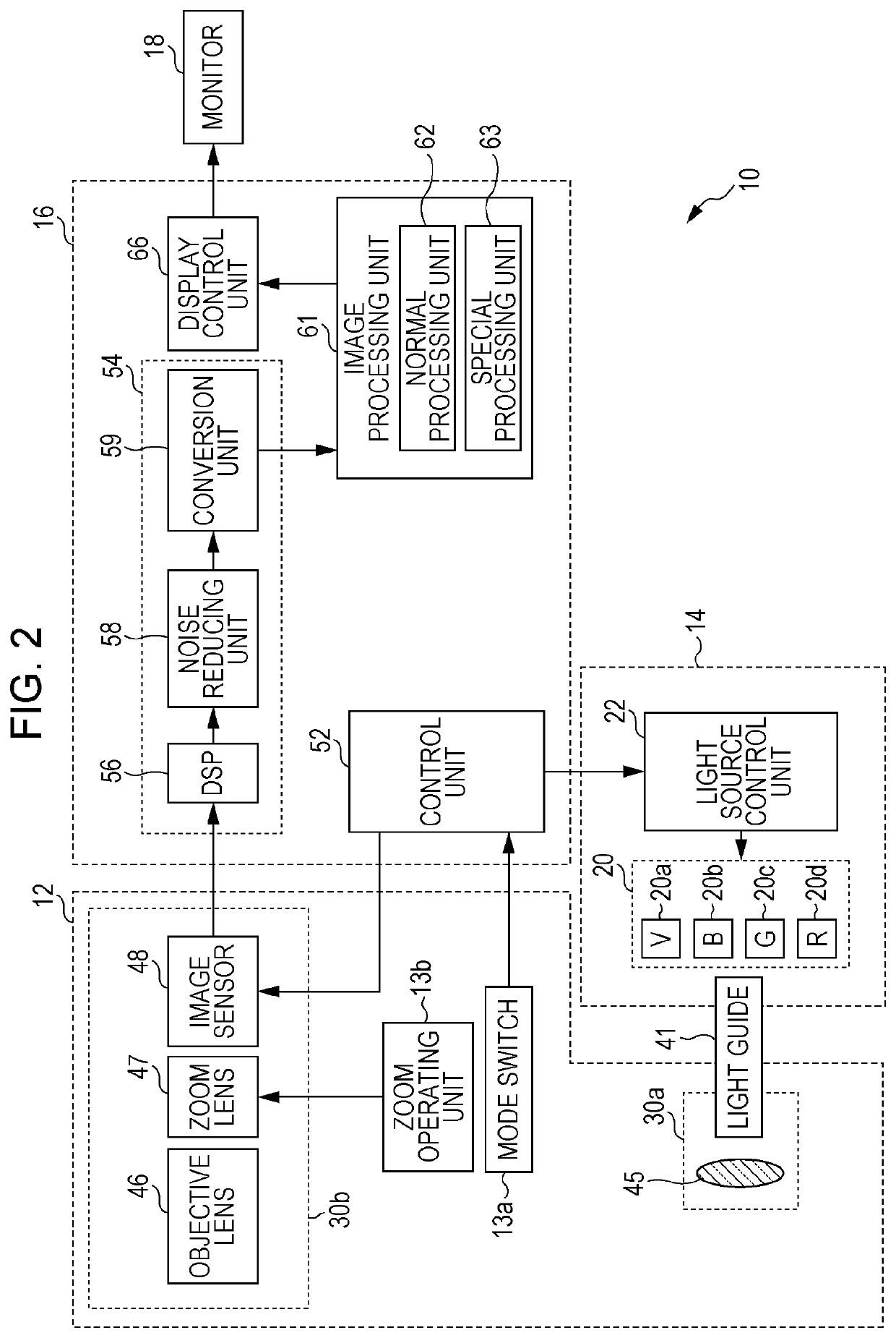
[0049]As illustrated in FIG. 1, an endoscope system 10 has an endoscope 12, a light source device 14, a processor device 16, a monitor 18, and a console 19. The endoscope 12 is optically connected to the light source device 14 and is electrically connected to the processor device 16. The endoscope 12 has an insertion part 12a to be inserted into a subject, an operating unit 12b provided at the base end portion of the insertion part 12a, and a bending part 12c and a tip part 12d provided at the distal end side of the insertion part 12a. Operation of an angle knob 12e of the operating unit 12b causes the bending part 12c to bend. As a result of the bending of the bending part 12c, the tip part 12d is oriented in a desired direction.

[0050]In addition, the operating unit 12b is provided with, in addition to the angle knob 12e, a mode switch 13a and a zoom operating unit 13b. The mode switch 13a is used for operation of switching an observation mode. The endoscope system 10 has a normal ...


PUM


Abstract

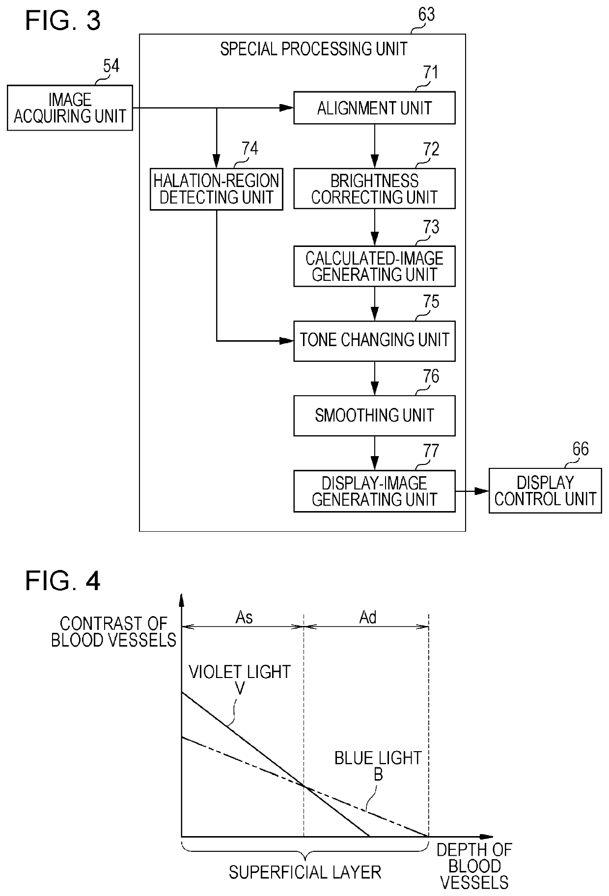
An endoscope system 10 includes an image acquiring unit 54 that acquires a first image and a second image, the first image being obtained by using first illumination light, the second image being obtained by using second illumination light at a different timing from the first image; a halation-region detecting unit 74 that detects a halation region; a calculated-image generating unit 73 that performs calculation by using the first image and the second image and that generates a calculated image; a display-image generating unit 77 that generates a display image in which a tone reflects the calculated image; and a tone changing unit 75 that changes the tone of the halation region in the display image.

Description

CROSS-REFERENCE TO RELATED APPLICATIONS[0001]This application is a Continuation of PCT International Application No. PCT / JP2016 / 084378 filed on Nov. 21, 2016, which claims priority under 35 U.S.C. § 119(a) to Japanese Patent Application No. 2015-250539 filed on Dec. 22, 2015. Each of the above application(s) is hereby expressly incorporated by reference, in its entirety, into the present application.BACKGROUND OF THE INVENTION1. Field of the Invention[0002]The present invention relates to an endoscope system that generates an image for display by using two images captured at different timings, a processor device, and a method for operating the endoscope system.2. Description of the Related Art[0003]In the medical field, with an endoscope system including a light source device, an endoscope, and a processor device, an observation target is typically observed and diagnosed by using an almost real-time motion picture. In addition, the following endoscope system is also known. The endos...

Claims


Application Information

Patent Timeline
Patent Type & Authority Patents(United States)
IPC IPC(8): A61B1/00H04N9/64A61B1/07A61B1/06G02B23/24H04N7/18A61B1/04
CPCA61B1/04A61B1/00009A61B1/00A61B1/00045A61B1/0669H04N7/18A61B1/00006H04N9/643G02B23/24A61B1/07A61B1/06A61B1/0638A61B1/041A61B1/0655A61B1/000095A61B1/000094H04N7/185G02B23/2484A61B1/044
Inventor AOYAMA, TATSUYA
Owner FUJIFILM CORP
Learn More